Continue to Site

Welcome to our site!

Electro Tech is an online community (with over 170,000 members) who enjoy talking about and building electronic circuits, projects and gadgets. To participate you need to register. Registration is free. Click here to register now.

  • Welcome to our site! Electro Tech is an online community (with over 170,000 members) who enjoy talking about and building electronic circuits, projects and gadgets. To participate you need to register. Registration is free. Click here to register now.

Electret microphone amp circuit ?

Status
Not open for further replies.

tron87

New Member
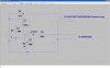
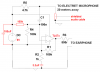
Looking for a some help in designing an amplifier circuit for a electret microphone that will output audio to a pair of cheap o mp3 earphones.I want to be able to adjust the output gain from 1-1000.

Do i go for common emitter transistor amp or non inverting op amp ?


I want to have 3 pots to control the circuit with 1 to control volume, 1 to adjust what low frequency are filtered and 1 to do the same as the second but filter high frequency out ?
 
Last edited:
It will take many transistors to make an amplifier with a gain of 1000 drive 32 ohm earphones that are 16 ohms when paralleled.
An opamp cannot drive 16 ohms but it can drive two complementary emitter-follower output transistors that can drive 16 ohms.
With a gain of 1000 a single opamp will cut all high audio frequencies so use two opamps in series, each with a gain of 32.

You will probably have acoustical feedback howling with a gain that is so high because the mic will hear the earphones.
 
Let's say a standard mic preamplifier supplies a Vpp of 150mV.

What do you want to connect to an output voltage of 150mV*1,000 (150V!)

Boncuk
 
Seems to me he should be able to use an IC preamplifier and 3 transistors for a power amplifier. Many circuits like this (or pieces that can be put together) out there.

So to the O.P., what I assume you mean by the other two potentiometers besides the volume (gain) control are standard tone controls (bass & treble), correct? These can easily be put in between 2 IC op-amp stages.
 
Thats correct bass and treble controls.

How do i know how much gain i need to make the mic as sensitive as possible without it getting stuck in a feedback loop ?


Im using a lm324 should the power supply pins always be say +9v and -9v or +9v and 0v ?


Just looking for a circuit that will do this i can only find amp circuit with either a bass or treble control but not both any suggestions ?
 
Last edited:
A lousy old LM324 is too noisy (hissss) to be a mic preamp. Also it has too much crossover distortion.
Use an audio low noise opamp like a TL071 single, TL072 dual or TL074 quad opamp. They can work from a single 9V supply like a 9V battery.

If a mic can hear the speaker or headphones then you will have acoustical feedback howling.

Google is full of bass and treble tone controls circuits like this one:
 

Attachments

  • Baxandall tone controls2.PNG
    Baxandall tone controls2.PNG
    12.7 KB · Views: 16,499
Last edited:
Im having some problems it works when the electret mic is on short lead <1 meter but anything over 4 meter + it picks up other radio stations and has a lot of interference how can i make it better.Ive added a rough and dirty schematic please help.
 

Attachments

  • Mic.JPG
    Mic.JPG
    117.3 KB · Views: 494
Last edited:
Your opamp has its (+) input connected to ground instead of to half the supply so it is a rectifier. It should be at half the supply voltage. Then the 1k resistor to ground must have a capacitor in series.
Also, low level audio signals are supposed to be connected with shielded audio cable.

The LM324 is much too noisy (hissss) to be a mic preamp. It has crossover distortion and a full output bandwidth of only to 1kHz. Use a low noise audio opamp like a TL071, TL072 dual or TL074 quad instead.

I will post a fixed schematic in a minute.
 
Last edited:
it picks up other radio stations and has a lot of interference how can i make it better.

Try following some of the suggestions from Audioguru. You're never going to get very good results using an LM324.

If you really do need to use a 20 metre lead at 'mic level' it's going to need to be screened. Even then, best avoided if possible.
Better to have the pre-amp and power amp (headphone driver stage) at the mic end, and have the 'long' lead connected to the headphone output.

Does mean running the DC power up to the mic end, but it will be much less likely to suffer from interference.
 
In North America we call a truck "a truck, dude", but elsewhere they call it a LORRY, MATE!
In North America we call Shielded Audio Cable "Shielded Audio Cable, dude" but elsewhere they call it SCREENED CABLE, MATE!
My wife is my mate and she is not a dude.

Here is the fixed schematic:
 

Attachments

  • mic preamp.PNG
    mic preamp.PNG
    32.7 KB · Views: 891
In North America we call a truck "a truck, dude", but elsewhere they call it a LORRY, MATE!
In North America we call Shielded Audio Cable "Shielded Audio Cable, dude" but elsewhere they call it SCREENED CABLE, MATE!
My wife is my mate and she is not a dude.

Well I guess we can usually work out what we both mean. Most words are the same.
Not quite sure how you always get on in Canada though. From what I read, if you live in certain parts, you are expected to learn to speak French!

Now that does have lots of different words!!
 
I learned real French in school. Then I visited Quebec where everybody speaks "French Canadian" but the dialect is very different from real French so I didn't know what they were saying. Like Cockney?
 
Like Cockney?

Not quite -- most people can understand a cockney accent OK. There are areas though, especially in the north of England and in parts of Scotland, where the accents are very strong, and very difficult to understand!

Accents are funny things though. Most Brits can't tell a US accent from a Canadian one, and most North Americans can't tell an English accent from an Australian one!

In danger of highjacking the thread here. Sorry!
 
On the first pic you posted Audioguru why does the output from the mic go to the inverting terminal on the op amp i thought signals from a mic just had to be amplified not also inverted ?


On the "fixed schematic" what does the capacitor do between r2 and gnd ?


On some schematics ive seen a capacitor in series with opamp output to the earphone why is this and what does it achieve ?


Whats the difference between changing the gain of a op amp and changing the amount of current to the earphone are they basically the same thing ?


Thx.
 
Last edited:
On the first pic you posted Audioguru why does the output from the mic go to the inverting terminal on the op amp i thought signals from a mic just had to be amplified not also inverted?
No.
My first pic is the line-level tone controls circuit that is fed from the very low impedance output of the mic preamp opamp.

On the "fixed schematic" what does the capacitor do between r2 and gnd?
It passes some of the the AC feedback signal to ground so that the opamp has lots of AC gain. But it blocks DC so the opamp has a DC gain of 1 so that the output idles at half the supply voltage like the (+) input, so the output can swing equally up and down with the signal.

On some schematics ive seen a capacitor in series with opamp output to the earphone why is this and what does it achieve?
A circuit with a single polarity supply causes the output of the opamps to be at half the supply voltage. You do not want to feed the DC voltage to an earphone so you use a coupling capacitor to pass the AC signal but block the DC. If the opamp has a dual polarity supply like this one then the output idles at 0V so the earphone will not have a DC voltage so it does not need the coupling capacitor.

Whats the difference between changing the gain of a op amp and changing the amount of current to the earphone are they basically the same thing?
Earphones are designed to be fed from a series 120 ohm resistor. A higher resistance will reduce the level a little but it might mess up the damping of resonances of the earphone. So a volume control is used at the input of the amplifier to adjust the level. Usually the gain is not changed, just the volume is changed.
 
Would wrapping a layer of foil around the microphone cable help shield it from picking up interference ?
Thx again
 
Would wrapping a layer of foil around the microphone cable help shield it from picking up interference?
Do you live in the jungle away from civilization?
Why don't you use shielded audio cable like everybody else? Many audio products come with shielded audio cables that people throw away because they use the old original cables.
 
You could say,would connecting lengths of earphone/headphone cable together do the same thing as proper "expensive" shielded audio cable on a reel ?
 
Earphone/headphone cable does not need to be shielded so usually it isn't shielded and cannot be used for a low level microphone.
RadioShack and The Dollar Store both sell the same shielded audio cables except RadioShack charges 10 times as much as The Dollar Store. It is cheap Chinese junk.

Shielded audio cable on a reel is not expensive. Microphone cable is expensive because it is thick and strong so it can be dragged across a stage many times.
 
Do you live in the jungle away from civilization?
Why don't you use shielded audio cable like everybody else? Many audio products come with shielded audio cables that people throw away because they use the old original cables.
[/quote]

Here I have to say--and I can hardly believe I'm saying this--that I agree with Audio McDuck. Unless you're in the jungles of Borneo, or some other place totally removed from the global village, just pay the twenty-five cents and get a piece of shielded cable. Buy a set of cables at the dollar store. Same stuff as at Rat Shack, just cheaper.
 
Status
Not open for further replies.

Latest threads

New Articles From Microcontroller Tips

Back
Top