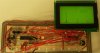
Here is an example of a simple spectrum analyzer I built with a dsPIC33FJ64MC802, AGM1264F GLCD and a 555 timer. The 555 was used to generate a 200-5000Hz square wave for test purposes. It is on the left side of the photo. I knew I'd find a use for a 555 timer one day. ") The LEDs in the center helped in debugging the GLCD routines.
The LEDs in the center helped in debugging the GLCD routines.
Since MicroChip supplies a DSP library which includes FFT routines and I had just received my GLCDs from **broken link removed**, I figured this would be a good challenge after my "Hello World" on a dsPIC. I wrote the code in 7 steps:
1) Hello world LED flashing and navel gazing.
2) Getting the ADC to output something meaningful to some LEDs.
3) Writing/testing some GLCD routines. (A little bit of futz's code in there)
4) Wrapping my head around FFT, complex numbers, etc.
5) Playing around with the MicroChip FFT library in SIM.
6) Writing a fast 16bit integer square root routine. No floating point here.
7) Integrating all of the above.
My to do list:
1) Make the span, resolution, etc, settings adjustable on the fly.
2) Add a LPF to the ADC input.
3) Bump up the dsPIC's clock and see how much bandwidth I can squeeze out of it. It is currently only clocked at 7.37Mhz and the display updates apx 4x a second. Span is 0 - 5000Hz in 39Hz steps. Not bad.
4) Compare it to a HP spectrum analyzer.
5) Clean up the bodged source code and post it.")
The LEDs in the center helped in debugging the GLCD routines.Since MicroChip supplies a DSP library which includes FFT routines and I had just received my GLCDs from **broken link removed**, I figured this would be a good challenge after my "Hello World" on a dsPIC. I wrote the code in 7 steps:
1) Hello world LED flashing and navel gazing.
2) Getting the ADC to output something meaningful to some LEDs.
3) Writing/testing some GLCD routines. (A little bit of futz's code in there)
4) Wrapping my head around FFT, complex numbers, etc.
5) Playing around with the MicroChip FFT library in SIM.
6) Writing a fast 16bit integer square root routine. No floating point here.
7) Integrating all of the above.
My to do list:
1) Make the span, resolution, etc, settings adjustable on the fly.
2) Add a LPF to the ADC input.
3) Bump up the dsPIC's clock and see how much bandwidth I can squeeze out of it. It is currently only clocked at 7.37Mhz and the display updates apx 4x a second. Span is 0 - 5000Hz in 39Hz steps. Not bad.
4) Compare it to a HP spectrum analyzer.
5) Clean up the bodged source code and post it.
 - box up the bread board in a case are you?

