Continue to Site

Welcome to our site!

Electro Tech is an online community (with over 170,000 members) who enjoy talking about and building electronic circuits, projects and gadgets. To participate you need to register. Registration is free. Click here to register now.

  • Welcome to our site! Electro Tech is an online community (with over 170,000 members) who enjoy talking about and building electronic circuits, projects and gadgets. To participate you need to register. Registration is free. Click here to register now.

Driving Stepper Motor

Status
Not open for further replies.

drkidd22

Member
I came around a stepper motor and I'm trying to figure out how to drive it. Currently I'm driving a smaller uni-polar motor with a PIC18F4520 and it's working ok.

The motors specs are:
0.59N.m holding torque
Rated current/Phase (Amps DC) = 2.0A
Phase resistance (ohms) 1.4Ohms
Voltage current/phase (DC) = 2.8VDC
Phase inductance (mH) = 3.

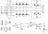
So does this mean that the motor can operate at a max of 2.8VDC and draw 2.0A (2.8VDC/1.4Ohms) per coil ? I'm going to be using the L298 chip and just want to make sure that I don't apply over voltage to the motor. The motor is Bipolar, 2 phase with a step angle of 1.8 degrees.
 
Yes, 2.8V coil voltage and 2.0 amps coil current is the maximum.

If you want to use a higher supply voltage you will need to add a power resistor in series with each coil to maintain the coil current and voltage below the maximum.

As a alternate you could use a transistor driver configured to deliver a constant current instead of using a resistor.
 
It is very common to use a much higher voltage than the stepper motor rating, because that allows the current to change very quickly, which means that the stepper motor can run faster.

Obviously, a much larger voltage will result in too much current unless something is done to limit the current. The resistors that Crutschow mentions is one way of doing it. A more complicated, but more efficient way is to have a PWM controller. Various ways of doing that are mentioned here:-**broken link removed**
 
Below is the schematic of the circuit that I would be using, I bought a controller board already built. I can do the PWM with the pic as well, but I'll like to know how I would limit the current into the motor coils. A power resistor sounds like a quick option which I would be using at each output between the motor and L298, but what other option do I have. How would I implement this using a PMOSFET?
 

Attachments

  • L298_H_Bridge.png
    L298_H_Bridge.png
    148.9 KB · Views: 207
The simplest solution is to use an L297 along with the L298. That uses smaller resistors to sense the current, and to control it by turning the supply voltage on and off.

The diodes should be Schottky ones and should be rated to 2 Amps or more.

If you are using a power switching IC like the L298, there would be no reason to have some other power switching element like a PMOSFET.
 
I found this AN470 that has lots of info in it and I should be able to complete my design with it. I'll replace the diodes with schottky ones, that's just the way the board came in with those 4007
 
Yes the 1N4007 are to slow you need faster diodes otherwise the chip may keep blowing. I have used BYV27-200-TR witch is a Ultra Fast Avalanche Diode.
The current senses resisters go between the sens A and B pins and ground, Can you isolate those pins on your board?
 
I might need to cut the trace to then solder the sense resistor, but I don't think I will need to use the sense resistor if I provide the correct PWM unless it is really needed by the L297. I'll have to see how it will work both ways. But in the case i do need a sense resistor I think a 0.5Ohm 3W resistor will do since the stepper I have can handle 2A, basically there will be 1V across the resistor causing 2W of power. I was trying to avoid the bulky resistor as I'm trying to keep the board I'm going to design lowest profile possible, but I'll make some readings and see what I'll get.
 
Status
Not open for further replies.

Latest threads

New Articles From Microcontroller Tips

Back
Top