Continue to Site

Welcome to our site!

Electro Tech is an online community (with over 170,000 members) who enjoy talking about and building electronic circuits, projects and gadgets. To participate you need to register. Registration is free. Click here to register now.

  • Welcome to our site! Electro Tech is an online community (with over 170,000 members) who enjoy talking about and building electronic circuits, projects and gadgets. To participate you need to register. Registration is free. Click here to register now.

Driving a pair of solenoids with a 555?

Status
Not open for further replies.
Hi EG,

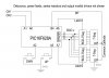
Can you please just check that you are working with the latest issue of the schematic of post #38.

Thanks

spec
So you did not change C1 (tant), but rather changed C3 (100nf) to the jumbo capacitor?
Also your driver chip: did you mean TC4428-CPA (DIP package)?
 
So you did not change C1 (tant), but rather changed C3 (100nf) to the jumbo capacitor?
Also your driver chip: did you mean TC4428-CPA (DIP package)?
Arrrraghh- I haven't woken up yet. Yes, C1. Schematic of post #38 corrected.

Yes, DIP package.

spec
 
Here is an idea with a simple Microcontroller with two switches to control the speed up or down.
 

Attachments

  • Dual_Sol_Drv_uC.jpg
    Dual_Sol_Drv_uC.jpg
    55.3 KB · Views: 126
  • Dual Solenoid Driver PIC12F683 TH.jpg
    Dual Solenoid Driver PIC12F683 TH.jpg
    142.1 KB · Views: 131
Updated Circuit Using a uC (PIC12F683). With two switches (up, down) the timing range could be set by increments of 1 seconds. Timer range from 1 seconds to 24 hours. Board size: 0.75"x 2"
project cost $3.00. The whole board can be placed in a small project box or placed in a shrink tube to protect it from the elements.
 

Attachments

  • Dual Solenoid NMOS Controller 12V 3A PIC12F683.jpg
    Dual Solenoid NMOS Controller 12V 3A PIC12F683.jpg
    123.3 KB · Views: 128
  • BottomCopper.jpg
    BottomCopper.jpg
    72.8 KB · Views: 126
  • Silk.jpg
    Silk.jpg
    100 KB · Views: 116
  • TopCopper.jpg
    TopCopper.jpg
    51.6 KB · Views: 123
Last edited:
Thanks EG. Looks pretty nice and pretty compact too. I don't think I have any PIC 12f series but I would consider building this just for fun. I will have to look at my component stash. I haven't taken time to get into it for a while. It's about time to build something just for the fun of it. What kind of code for the PIC?

Thanks.
rfranzk.
Hi RF
I have not written the assembly code since I got busy with work. But the concept is very simple. It first sets a delay time. Then program will check both SW inputs for SW push. If up is pushed, delay is incremented. If down is pushed then delay is decremented. The third option is when SW1 and SW2 are both pushed which will set the delay in minutes. Then up or down sw push will change the minutes.
After the delay is set and the value is saved, the code will proceed with Sol1-on Sol2-off, then the saved delay, then Sol1-off Sol2-on, then delay again. Then it goes back and checks SW's status again.

Instead of PIC12F (small package), you can switch to PIC16F (more outputs). Use 7 bits for 7-segment, 3 outputs for positive feeds of 3-digit 7-seg (multiplexing 3x 7-seg). 2 Outputs for NMOS drivers. Push buttons for Up and Down, Push buttons for Minutes/Seconds mode change.
Regards,
EG
 
...I haven't taken time to get into it for a while. It's about time to build something just for the fun of it....

Thanks.
rfranzk.
RF
If you are planning to build a useful project for yourself (for the fun of it or the challenge), then I would suggest you to start with your concept and set some basic specifications. Then you can look for solutions as how to implement your project.
Here is an example: I want...
- A timer that runs two solenoids in a toggle configuration (one ON at a time)
- To be able to set on/off time and to be flexible from 1 second to 1 minute (or other ranges)
- The time to be displayed on a 7-segment in seconds and minutes (how many digits)
- Interact with it and be able to set the time using minimum switches (or dip switches, or a potentiometer)
- The circuit to be digital, analogue, or be micro-controller based
- Not to cost more than certain amount (or work with certain parts you already have in your toolbox)
- Not to exceed certain size (specific dimension) as I am placing it in a project box
and so on....

Watching up to now. I would suggest to also consider the condition when the governing timer's PSU is off.

Maybe the application could require one specific pair of contacts being necessarily NO (or NC). Separate PSUs...?

Not sure if I am adding a complication that does not exist...:(
 
Watching up to now. I would suggest to also consider the condition when the governing timer's PSU is off.

Maybe the application could require one specific pair of contacts being necessarily NO (or NC). Separate PSUs...?

Not sure if I am adding a complication that does not exist...:(
Hello ATF
Not sure what you mean. Are you saying to account for a case where you want the timer on but Solenoids off? This can be solved with a switch between middle leg of output (12v) to both solenoids.
If PSU is off then the solenoids are both off (referring to NMOS circuit)! If a relay is used instead of NMOS's then yes you need to shutoff power to the solenoids so both solenoids are off. This is more important if you use two PSU circuits.
So I am not sure if you are suggesting two seperate PSU or something else.
Regards,
EG
 
As Suggested Above. 2-Digit NMOS version with 7-segment and PIC16F628a.
Although two digits only displays up to 99, the timer can be extended beyond that in minutes and seconds.
Press set (display single flash indicating program mode), enter minutes, press set, enter seconds, press set and hold until display double flashes indicating time is saved to memory. This puts a default time in the memory and on power-up this time is loaded.
Press up or down to change seconds during operation. Press min/sec button to toggle between minutes and seconds, allowing up/down adjustment.

Edit: Board dimensions are approx. 1.5"x3"
 

Attachments

  • ALL.jpg
    ALL.jpg
    326.8 KB · Views: 136
  • BOTTOM.jpg
    BOTTOM.jpg
    185.9 KB · Views: 117
  • SILK.jpg
    SILK.jpg
    230.9 KB · Views: 107
  • TOP.jpg
    TOP.jpg
    129.2 KB · Views: 122
Last edited:
Hello Everyone,

Thanks for all the input to this project. Greatly appreciated. I did find a commercial solution to this system and have used it once. Not perfect but acceptable for now. I will probably build something in the future that exactly suits the needs of the project and this micro unit looks pretty good.

Thanks again,
rfranzk.
 
Here is the optimized PCB. If anyone is interested, I can create the Schematics, BOM and Gerber files in Kicad.

Edit 2/1/2017: Flowchart for Simplified Timer upload. 2 Switches Only (Up & Down), PCB to be modified, Two digit timer 1-99 seconds (no minutes). User sets the default time delay, from there on up and down sw's adjust the timer in seconds. Upon power down (reset), timer goes back to the default time delay.
 

Attachments

  • Bottom.jpg
    Bottom.jpg
    240.1 KB · Views: 114
  • PINOUT_MAPPING.jpg
    PINOUT_MAPPING.jpg
    186.4 KB · Views: 126
  • Silk.jpg
    Silk.jpg
    237.8 KB · Views: 111
  • Top.jpg
    Top.jpg
    227.1 KB · Views: 114
  • 7-SEG_TO_PIC_MAPPING.jpg
    7-SEG_TO_PIC_MAPPING.jpg
    223.4 KB · Views: 117
  • Dual_Sol_Timer_Flowchart.png
    Dual_Sol_Timer_Flowchart.png
    112.2 KB · Views: 118
Last edited:
Hardware Updated, two LED Drivers and series resistors added. This removes requirement for multiplexing of 7-segments. Each digit is driven with a BCD to 7-Segment Latching (and blanking) driver. This mean once time is read and displayed, it can be latched to free up PIC to rapidly test SW-presses and run the solenoids without any timing constraints. Also DP LED of both digits are tied together and will blink each second during operation. Next I will be working on the code

Updated Version uploaded. In this version, the drivers are nicely tucked in under the 7-seg.
 

Attachments

  • Dual Solenoid NMOS 7-SEG 12V 10A PIC16F628A V10.jpg
    Dual Solenoid NMOS 7-SEG 12V 10A PIC16F628A V10.jpg
    336 KB · Views: 128
  • Dual Out 2-Dig 7-SEG 12V 10A PIC16F628A.jpg
    Dual Out 2-Dig 7-SEG 12V 10A PIC16F628A.jpg
    243.6 KB · Views: 113
Last edited:
EG,
Looks really nice. Thanks for your efforts. At this point I purchased something that works but I like this and am going to construct it. I haven't been to active here lately as there are some family health issues requiring additional time from me.

Thanks again.

rfranzk.
 
EG,
Looks really nice. Thanks for your efforts. At this point I purchased something that works but I like this and am going to construct it. I haven't been to active here lately as there are some family health issues requiring additional time from me.

Thanks again.

rfranzk.
Hello RF
I have not built the circuit or tested the code yet. But, I will create a new thread and post the project. That way you or anyone else can follow and contribute.
Regards,
EG
 
EG,
Looks really nice. Thanks for your efforts. At this point I purchased something that works but I like this and am going to construct it. I haven't been to active here lately as there are some family health issues requiring additional time from me.

Thanks again.

rfranzk.
Here is a simplified circuit from logic point of view.
 

Attachments

  • Dual Out 2-Dig Timer.jpg
    Dual Out 2-Dig Timer.jpg
    113.2 KB · Views: 103
Status
Not open for further replies.

Latest threads

New Articles From Microcontroller Tips

Back
Top