Continue to Site

Welcome to our site!

Electro Tech is an online community (with over 170,000 members) who enjoy talking about and building electronic circuits, projects and gadgets. To participate you need to register. Registration is free. Click here to register now.

  • Welcome to our site! Electro Tech is an online community (with over 170,000 members) who enjoy talking about and building electronic circuits, projects and gadgets. To participate you need to register. Registration is free. Click here to register now.

Driving a pair of solenoids with a 555?

Status
Not open for further replies.

rfranzk

Member
Hello All,

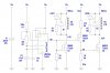
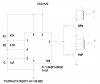
I am in need of a circuit to drive a couple of 12 volt dc solenoids 7 watt at alternating on off cycles of approximately 30 seconds to one minute. I was thinking of using a single 555 and driving one npn transistor and one pnp transistor from a 555 output. I don't know if that is feasible or even possible. The circuit needs to be fairly robust and able to drive these two solenoids for 1 to 2 hours continuously. So when one solenoid is on the other is off and then switching states at 30 second to 1 minute intervals.

The solenoids are rated at 7 watts and I will be powering the circuit with a regulated 12 volt 10 amp supply. I measured the resistance of the solenoid coil at 22 ohms and that gives current of 12/22 =.545 amps. I would like to use bipolars or mosfets capable of at least one amp to provide a little margin. The timing is not critical and some adjustment would be handy and a 50% duty cycle is just right.

I can build almost anything but design is out of my league at this point in time. Something I am gradually learning.

Any help would be appreciated.

Thanks. rfranzk

20170116_164039.jpg
 
Hi RF

alternating on off cycles of approximately 30 seconds to one minute.
Could you explain specifically what you mean.
Is my understanding correct:
(1) When one solenoid is on the other solenoid is off
(2) You would like the on and off period to be the same length
(3) You would like to have the on period adjustable from 30 seconds to 60 seconds
spec
 
Try this. 2N4403 (PNP), 2N4401 (NPN), complimentary pair can handle 600ma at Vce saturation of 0.4v. So Power Diss of each transistor is about 235mw which is within 625mw spec. You should be good to go. Base resistors of 820 to 1k for both transistors (gain about 50). If you need more power, you can switch to darlington pairs, or Mosfets.
 

Attachments

  • DUAL-SOL_555Timer.jpg
    DUAL-SOL_555Timer.jpg
    187.8 KB · Views: 237
Last edited:
Last edited:
Could you explain specifically what you mean.
Is my understanding correct:
(1) When one solenoid is on the other solenoid is off
(2) You would like the on and off period to be the same length
(3) You would like to have the on period adjustable from 30 seconds to 60 seconds
spec

Hello Spec, Yes to all of the above. The circuit you posted looks nice and I am curious about the need for the IR4428. My initial thoughts were to try something like was posted by EG at post #3. I won't have much time to review this until later this evening.

Thanks to EG and Spec for your input.

rfranzk.
 
Hello Spec, Yes to all of the above.
Thanks- so I got it right.:)
The circuit you posted looks nice
Nice of you to say so.
I am curious about the need for the IR4428.
I am not surprised. The IR4428 is way overkill for this application. But ask yourself in what way is it overkill. The IR4428 costs next to nothing, is freely available and is in a nice 8 pin pack. Why not?
My initial thoughts were to try something like was posted by EG at post #3.
EG's approach is fine. But I would argue that it is more complicated than just a singe chip and the performance would not be comparable (but perfectly adequate).

spec
 
Last edited:
Referring to post #3, moving 545 mA through a part rated for 600 mA is not god for long term reliability. The rule of thumb is that all parts run at no more than 50% of their ratings.
12 V circuit > 25 V capacitors min.
1 W power > 2 W resistor min.
545 mA collector current > 1 A to 2 A transistor min.
etc.

Also, 30-60 s is a loooong time for a single R-C timer stage. I recommend a single chip oscillator-divider (CD4060) as a way to get long periods without huge capacitors. For 30 s on / 30 s off. a 555 would run at 1 Hz. A 4060 would run at 16,384 Hz. Schematic to follow.

ak
 
Spec, in your schematic you have drawn N channel mosfets but stated IRF9540 which is a P channel mosfet. Also, isn't a 23A mosfet a little overkill for half an amp.:)

Mike.
 
Spec, in your schematic you have drawn N channel mosfets but stated IRF9540 which is a P channel mosfet. Also, isn't a 23A mosfet a little overkill for half an amp.:)

Mike.
Thanks Pommie- I like to make big mistakes:D

A 23A MOSFET is definitely overkill but, like the gate driver chip, this is a good thing as there are performance benefits but no cost or size penalties.:)

But the SOA is often the limiting factor rather than the junction temperature.

And if you do not keep RDss down you end up having to use a heatsink even at 0.5A.

spec
 
Assuming a sot3 package can manage 0.1W then anything with a Rds below 0.2Ω will do the job. A Farnell search turns up the FDN327N. This should only have to dissipate 7mW.

Edit, Also, with such a slow time period and a low gate charge, you could use the first to drive the second and eliminate the driver chip.

Mike.

Yes, that is all quite true and would have the advantage of a physically smaller layout.

(best swap discharge and Q on the LMC555 though)

Of course, you would have to put limiting Zener diodes between gate and drain of the FDN327N NMOSFETs.

But most home constructors do not like working with surface-mount.

Are you going to post your circuit?

spec
 
Last edited:
Here is a Robust version for your review. On the secondary solenoid, I used two complimentary mosfets to lower the voltage drop on Q3. Both Nmos transistors have an approximate 0.3v Vds and can handle many amps as your heart desires. 1 amp TO-220 package without a heatsink is more than sufficient.
Also keep in mind Vout on pin3 of 555 is 2/3Vcc (= approx 8v). The R4 and R5 are selected to provide approximately the same (8.1v) at the gate of Q3.
Regard
EG

Edited: LED'S ADDED, PMOS Pins Corrected. Thanks Pommie
 

Attachments

  • 2-SOL 555 CIRCUIT.jpg
    2-SOL 555 CIRCUIT.jpg
    227.7 KB · Views: 211
Last edited:
Evil, you have your pmos upside down. And, why not replace the 1k with the second relay and do away with the third fet.

Using the nmos I posted above a 50% voltage divider from the 555 would drive the first gate. The second gate could be driven by another divider from the junction of the first nmos and relay.

No circuit as no drawing package available at the moment.

edit, or choose a more suited nmos and get rid of dividers.

Mike.
There are many ways to skin this cat. Thank you for PMOS correction.
You can also do this with two opto-couplers and then connect the outputs to two NMOS. One uses logic positive and the other uses logic negative.
Regards,
Rom
 
Referring to post #3, moving 545 mA through a part rated for 600 mA is not god for long term reliability. The rule of thumb is that all parts run at no more than 50% of their ratings.
12 V circuit > 25 V capacitors min.
1 W power > 2 W resistor min.
545 mA collector current > 1 A to 2 A transistor min.
etc.

Also, 30-60 s is a loooong time for a single R-C timer stage. I recommend a single chip oscillator-divider (CD4060) as a way to get long periods without huge capacitors. For 30 s on / 30 s off. a 555 would run at 1 Hz. A 4060 would run at 16,384 Hz. Schematic to follow.

ak
I agree with your assessment as I put up a beefier one. However remember 555 is also modulating! I believe 2N4401 and 03 can take peak current of up to 1A. I would not push it that way but just saying. It is more of power dissipation that will kill it rather than just plain current. If Vbe is low enough (0.4v) then at 600ma you would burn up 240mw! If modulating, then you can push the envelope a bit if you need to. As I said, I am not arguing with your valid point and if I had an expensive solenoid like the picture, I would do it right and spend couple of extra dollars to have a solid circuitry. I also like the circuit Spec put up. Mine was a 3 minute post without calcations. My beefier circuit is simulated.
Regards
EG
 
Thanks to everyone for the well thought out suggestions. I am real busy at the moment and probably won't be able to do much with this project for a week or two. While looking at things a couple of more ideas came to mind. I would like to add a couple of led's to indicate which solenoid is powered on. I assume I could add led's with current limiting resistors in parallel with the load and the protection diodes across the solenoids? It would be nice to be able to adjust frequency from 5 seconds to 1 minute. Does that just require a change in resistors or capacitors? Both circuits are very robust. Thanks Very Much.

rfranzk
First thing to correct. In post#3 the pulse time is inaccurate. Using those values (47k, 4.7k, 1uF) you get 39 seconds (not 60 sec).
Now to answer your question of being able to change the speed, change the resistors and capacitor of 555 circuit with the following values:
C=1uF, R2=1k, and replace R1 with two resistors in series. One is fix 5k in series with a potentiometer of 100k.
So in this format R1 value changes from 5k to 105k, changing your time delay from 5 seconds to 74 seconds approx.
As for your LED, putting it in parallel with the diode up there, as you mentioned, might unintentionally create an oscillation. I would rather put the LED and its series resistor in parallel with gate to source of Nmos (this already has a Gate-Source diode of 1v to 1.5v so it wont do much harm).

Hi EG,

I suspect your timing is still too short. The requirement is 30 seconds to 60 seconds on and off period. Being lazy, and using a ball-park calculation, 100K and 1UF give a time constant of 100 milliseconds. Post #4 shows a time constant of 47uF and 2M = 95 seconds when the frequency potentiometer is at its maximum resistance and 47uF and 22K = 1 second when the potentiometer is at its minimum resistance, so the timing provided includes the OPs requirements and more.

By the way, the 47uF timing capacitor is a tantalum type for lower leakage current compared to an aluminum type. The Rolls Royce approach would be to use a polypropylene (PP) timing capacitor, but a 47UF PP capacitor would be big and expensive. The value of the timing capacitor could be reduced by an order by increasing the 2M potentiometer to 20M, but such a high value would not be advisable as any humidity may affect the timing.

AK's suggestion of using a digital period generator would provide a Rolls Royce plus performance but with more cost and complexity.

Notice that I have specified an LMC555 rather than an LM555. An LMC555 has a much higher input impedance on its TRIGGER and THRESHOLD pins and its ouput swings rail to rail. The C MOS version of the 555 has other benefits too.

I looked at a few circuits to implement this function and, so far, the simplest, but not best performing, would be to use an LM339 quad comparator for period generation and driving two NMOSFETs which, in turn, powered the solenoids.

But, as you imply, there are more ways than one of killing a cat than by poking its eyes out with a sharp stick.:D

spec
 
Last edited:
Hi EG,

I suspect your timing is still too short. The requirement is 30 seconds to 60 seconds on and off period. Being lazy, and using a ball-park calculation, 100K and 1UF give a time constant of 100 milliseconds. Post #4 shows a time constant of 47uF and 2M = 95 seconds when the frequency potentiometer is at its maximum resistance and 47uF and 22K = 1 second when the potentiometer is at its minimum resistance, so the timing provided includes the OPs requirements and more.

spec
Long day grasshopper. I am not sure why i was thinking k.k.uF will cancel each other out. It is K.uF with 1/1000. Last OP's post was 5-60 seconds. So I am off by a factor of 1000 on the resistor. T=(R1+2R2)C/1.44, For equal charge discharge T=RC/0.72
As forest gump would say. That's all I have to say about that...
 
Nice to see that you are human EG.:)

Makes me feel a bit better about my many mistakes.

You know what Confucius say grasshopper, "Anyone who has not made a mistake has not made anything either.":D

spec
 
Last edited:
Status
Not open for further replies.

Latest threads

New Articles From Microcontroller Tips

Back
Top