Continue to Site

Welcome to our site!

Electro Tech is an online community (with over 170,000 members) who enjoy talking about and building electronic circuits, projects and gadgets. To participate you need to register. Registration is free. Click here to register now.

  • Welcome to our site! Electro Tech is an online community (with over 170,000 members) who enjoy talking about and building electronic circuits, projects and gadgets. To participate you need to register. Registration is free. Click here to register now.

Draining capacitors on power supply

Status
Not open for further replies.

hfireworks

New Member
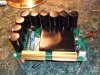
I have built a capacitive discharge system for my electronic firing system and I have (9) 200vdc 220uf capacitors that charge up from the power supply.

I am needing to use a resister to slowly drain the capacitors once power is turned off. I am using Dale aluminum RH-560 50W 1.5 ohm on my power supply to generate the 200vdc power load.

I would like to use (1) resister to slowly drain all (9) separate power lines, these are individual power lines but I would like to slowly drain all of them with one resister.

What do you recommend, and do you have a diagram that can be put to use?
 

Attachments

  • power panel.JPG
    power panel.JPG
    201.8 KB · Views: 479
The caps probably won't care about discharge rate. Old rounded-off screwdrivers used to do the trick real well, although they would occasionally weld onto terminals. If you want to use a switch and have it last, grab a 10 watt 1000 ohm sand resistor and switch it across the caps. Just leave it connected for 10 minutes and all charge will be gone.
 
j.p.bill said:
The caps probably won't care about discharge rate. Old rounded-off screwdrivers used to do the trick real well, although they would occasionally weld onto terminals. If you want to use a switch and have it last, grab a 10 watt 1000 ohm sand resistor and switch it across the caps. Just leave it connected for 10 minutes and all charge will be gone.

My power supply is rated at 35watts.
This is a High Voltage power supply for fireworks discharge and I need something to be internal

I would not rather us a switch.
Can this be left on permanetly, Not the screwdriver done that, I would like to design it on my board so the power supply works as normal but when I turn off power to the supply the cap will drain and not leave high voltage on the board.
 
Last edited:
I would like to use (1) resister to slowly drain all (9) separate power lines, these are individual power lines but I would like to slowly drain all of them with one resister.
Since these caps are not in parallel and are totally separate; connect a resistor of sufficient value and wattage across each capacitor. This is called a bleeder resistor. It's value depends on the voltage across the cap and how long you are willing to wait for it to discharge to a safe level.
 
kchriste said:
Since these caps are not in parallel and are totally separate; connect a resistor of sufficient value and wattage across each capacitor. This is called a bleeder resistor. It's value depends on the voltage across the cap and how long you are willing to wait for it to discharge to a safe level.

You are right they are not in parallel and are totally separate, would I have to use a large 35W aluminum resistor to accomplish this, my power supply is at 200vdc and I am using 220uf caps.

Bleeder resistor is what I am looking for and the discharge time is not relevant as long as it does discharge slowly.
 
I would use a 1/2watt 150K:eek:hm: resistor across each cap in a trade off between wasted power, heat, discharge time, and cost. Should take about a minute for the caps to discharge to a safe level.
 
hi,
You could use a suitably rated domestic mains filament lamp as a load dump.

In the UK, most domestic lamps are rated at 240Vac, if you chose say, a 25Watt version,
this would drain the caps to zero quickly and safely.
 
ericgibbs said:
hi,
You could use a suitably rated domestic mains filament lamp as a load dump.

In the UK, most domestic lamps are rated at 240Vac, if you chose say, a 25Watt version,
this would drain the caps to zero quickly and safely.

That too is a good possibility, I could place the lamps on my panel, to verify that the power has been drained. However the 200vdc output at 35watts of the lamp will be bright.

I do not want the voltage to drop very quickly, as to be a drain on my main 24vdc batteries to keep the capacitors in full charge during operation.
 
Last edited:
hi,

There are 'pygmy' versions of the lamps down to 15Watts and less, in different colours.
Low energy types, if suitable, as low as 3Watts.
 
Last edited:
hfireworks said:
I do not want the voltage to drop very quickly, as to be a drain on my main 24vdc batteries to keep the capacitors in full charge during operation.

Why bleeds the capacitors and drain energy while the system is in standby/use? Fits a 24V relay at the supply side to switch OFF the bleeding resistor when 24V supply is healthy.

If all the 9 capacitors have a common negative connection, then it might be possible to connect up all positive terminal of the capacitors to a common point using blocking diodes and discharge all 9 capacitors with a single resistor.
 
Use some 250V mosfets with bleed resistors in drain. One button press (tied to all the gates) could turn them all on and discharge each C with its own resistor. BTW, you do not need high watt ratings for the discharge resistors in this case because they are not always in circuit dissipating power. They only switch in when you signal to discharge.
 
eblc1388 said:
Why bleeds the capacitors and drain energy while the system is in standby/use? Fits a 24V relay at the supply side to switch OFF the bleeding resistor when 24V supply is healthy.

If all the 9 capacitors have a common negative connection, then it might be possible to connect up all positive terminal of the capacitors to a common point using blocking diodes and discharge all 9 capacitors with a single resistor.


So typically using the 9 blocking diodes to prevent backflow from the 9 Capacitors I can connect all 9 capacitors to a block and using a single switch to discharge all 9 capacitors into a single resistor.

So, if I switched all 9 capacitors into a single resistor, I would have 9 200vdc 220uf caps. Would one Dale RH-50 50watt 1.5k aluminum resistor handle that kind of power to drain?

If that were the case I could add a swich, possibly a high power SCR, or Darlington Pair or a relay to a toggle and add an LED and discharge.
 
Last edited:
Optikon said:
Use some 250V mosfets with bleed resistors in drain. One button press (tied to all the gates) could turn them all on and discharge each C with its own resistor. BTW, you do not need high watt ratings for the discharge resistors in this case because they are not always in circuit dissipating power. They only switch in when you signal to discharge.


I havn't used mosfets yet but read a little on them, I am beginning to se the bigger picture on this now, The design is popping into my head.

Since the capacitors have an abundance of power stored, could connecting all 9 of them create a surge on the resister?
 
j.p.bill said:
The caps probably won't care about discharge rate. Old rounded-off screwdrivers used to do the trick real well, although they would occasionally weld onto terminals. If you want to use a switch and have it last, grab a 10 watt 1000 ohm sand resistor and switch it across the caps. Just leave it connected for 10 minutes and all charge will be gone.


I am curious as to the 10 watt 1000 ohm sand resistor I have not seen one, what are the characteristics of these?
 
We usd to have some pin welders, they used capacitive discharge for spot welding pins that held insulation in place on large air conditioners. They had a relay wired across the caps that when power was shut off, the normally closed contacts would put a resistor (value ?) across the caps. The resistor would discharge the caps over a 3-4 minute time period. The open circuit voltage was variable from 70-180 vdc, and the discharge time would vary.
Asand resistor is about 3/8 square by about 1 1/2 long and looks like a tan colored ceramic , inside is usually a wirewound resistance.
Hope this helps..
 
hfireworks said:
So typically using the 9 blocking diodes to prevent backflow from the 9 Capacitors I can connect all 9 capacitors to a block and using a single switch to discharge all 9 capacitors into a single resistor.

Yes, if the capacitors all have common negative connection.

hfireworks said:
So, if I switched all 9 capacitors into a single resistor, I would have 9 200vdc 220uf caps. Would one Dale RH-50 50watt 1.5k aluminum resistor handle that kind of power to drain?

This is how I estimate the wattage of the resistor, for a one off, infrequent discharge operation. The initial wattage is calculated as usual, using the V*V/R formula, giving 26W for a 1.5K resistor. However, as the discharge current is not constant but reducing quickly, it is possible to select a smaller wattage resistor in this case. I would go for a 20W or 15W aluminum resistor in this case.

hfireworks said:
If that were the case I could add a swich, possibly a high power SCR, or Darlington Pair or a relay to a toggle and add an LED and discharge.

Yes.
 
All capacitors do have a common ground.

This is getting clearer to me now, I don't think I will have a problem.

I can test a few of these and make my best choice for this situation.

I do want a mosfet, SCR, relays or some sort of high voltage trigger switch to handle the voltage and save my switch.

This has been a lot of help in my power supply design.

I should be able to use a 1000v diodes to get this done.

I have seen the sand resisters just did not know they were called that.
 
They are wirewound resistors in a light brown rectangular molded case. The "bottom" is a white, grainy substence that is cast in place, and looks like sand. For the wattage, they are quite inexpensive.

To figure the resistor to use, calculate the RC time - that's the product of the capacitor (220 mikes) time the resistance (your choice). The time to charge a cap through a resistor is about 5RC, so the discharge time ought to be about the same. The size of the resistor will give you the current - I = E/R, so you can use the current figure to get to the resistor wattage - P = I squared R. You may very well not need 10 watt resistors.
 
j.p.bill said:
They are wirewound resistors in a light brown rectangular molded case. The "bottom" is a white, grainy substence that is cast in place, and looks like sand. For the wattage, they are quite inexpensive.

To figure the resistor to use, calculate the RC time - that's the product of the capacitor (220 mikes) time the resistance (your choice). The time to charge a cap through a resistor is about 5RC, so the discharge time ought to be about the same. The size of the resistor will give you the current - I = E/R, so you can use the current figure to get to the resistor wattage - P = I squared R. You may very well not need 10 watt resistors.

Capacitor calculations can get a little complicated, I have changed my caps on my power supply 3 times, started with 100uf went to 470uf and back down to 220uf. May very well go back to 100uf.

Capacitors have a tendency to charge slowly to 100% full charge, they may start at 60% and with the charge discharge they gradually increase to 100% making it harder to determine which caps to use.

These calculations will help.

Thanks
 
Status
Not open for further replies.

Latest threads

New Articles From Microcontroller Tips

Back
Top