versimilitude
New Member
Firstly, i'd like to apologise because my base electronics isn't great! I have started to mess about with some electronics and am slowly learning.
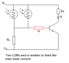
I've created a simple light activated switch as per the attached drawing. It works great but now i'm getting a little more adventurous! I now want to use two LDRs so that when either of them senses light the single LED will come on.
any help anyone can give to point me in the right direction would be much appreciated.
Thanks!")
I've created a simple light activated switch as per the attached drawing. It works great but now i'm getting a little more adventurous! I now want to use two LDRs so that when either of them senses light the single LED will come on.
any help anyone can give to point me in the right direction would be much appreciated.
Thanks!