Continue to Site

Welcome to our site!

Electro Tech is an online community (with over 170,000 members) who enjoy talking about and building electronic circuits, projects and gadgets. To participate you need to register. Registration is free. Click here to register now.

  • Welcome to our site! Electro Tech is an online community (with over 170,000 members) who enjoy talking about and building electronic circuits, projects and gadgets. To participate you need to register. Registration is free. Click here to register now.

DIY bluetooth speaker

Status
Not open for further replies.
Thread re-opened at OP request.

JimB
 
Thank you JimB !! :)

Didn't do any new speaker in a while but i get an idea from time to time. So i have a question now.

Since my speaker is battery powered it is important to make it as efficient as possible. Right now its a 2 way: TCP115 4" woofer and a small tweeter capped at 3500Hz. But i was looking at sensitivity of the TCP115 4" and compared it to some midrange or full range speakers and between 150Hz and 3500Hz those speakers are more efficient - have better sensitivity.

So i am asking, theoreticaly, would my speaker be more energy efficient if i changed my woofer/tweeter 2 way into this:

TCP115 4" woofer 30 - 150Hz
Midrange 150Hz - 3500Hz
tweeter 3500Hz - 20.000Hz
 
Hi. It has been a long time so I forgot most of your thread.

I think 150Hz is too low for a midrange speaker. Is your TCP115 8 ohms or 4 ohms? A 4 ohms speaker's amplifier uses double the battery current to make double the output power.
A Visaton 2" cheap 8 ohms speaker has the same sensitivity as the TCP115 4 ohms but no frequency response graph.
The Visaton 2.5" cheap 4 ohms speaker has the same sensitivity as the TCP115 4 ohms then you gain nothing.

Larger woofers move more air then are more efficient (higher sensitivity).
 
Question about crossover. I am using dayton audio TCP115-4 woofer and dayton audio ND16FA-6 woofer. I added graphs of both in the attachment for u to see. Now for tweeter itself, it says frequency response 3500-27.000Hz. But on the graph u can see even under 3000, there is some power, even though it is dropping. For TCP115-4 u can see its dropping at above 1500Hz rapidly.

My question is: how long i can go on a tweeter without damaging it. Lets say i make 1st order crossover on tweeter at 2000Hz, will i damage it ? As u know, i am all about loudness per Watt, quality comes second. How long can this tweeter go without getting damaged ?

Here is the link to the tweeter:


Attachments

  • tweeter.JPG
    tweeter.JPG
    76.4 KB · Views: 183
  • woofer.JPG
    woofer.JPG
    63.1 KB · Views: 178
Years back Wharfedale (the famous speaker company) inadvertently fitted the wrong crossover in a couple of their speaker ranges, as the crossover was too low the cones moved further than they should, snapping the wires between coil and terminals. I know this, because I had a pair that failed, and I spoke to their Managing Director who explained the problem to me, and sent me new tweeters and correct crossovers to repair them.

A first order crossover is pretty crappy anyway, and you're likely to be feeding far too much low frequency power to the tweeters to start with, and having too low a frequency will just make that worse. Doesn't the tweeter manufacturer provide crossover examples.

Other wise, don't turn the volume up - which is where the danger lies.
 
Ok, i will try to stay at around 3000Hz then just to be safe. Another question. I am suplying 25V to my bluetooth amplifier and it is a 2x50W amplifier. I will be buying a capacitor to do a crossover. Since i am suplying 25V to it, is a 25V capacitor ok ? Or is that 25V getting stepped up to a higher voltage on the amp itself ? I am asking because most cheap unipol capacitors are 25V.

edit: I found a formula for necesary voltage, can u verify that this is correct: V = sqrt(W * R) where R is impedance of speaker. In my case i have 6 ohm tweeter thats 10W (but the channel is 50W), so worst case scenario we have V = sqrt(50W * 6 Ohm) = sqrt(300V) = 17.3V, which would mean 25V is plenty.
 
Last edited:
I cannot remember it and could not find it in a search of your old postings here. Please post the datasheet of the 2x50W amplifier.

The amplifier is probably bridged (an amplifier for each speaker wire) which effectively almost doubles its output voltage swing and doubles or more its output power.
Your 25V power supply voltage is doubled to 50V and has a voltage loss of about 6V so the peak-to-peak output voltage is 44V which is 15.6V RMS. Then the output power at low distortion is 30.4W into 8 ohms or 50W into 4 ohms. Your 6 ohms tweeter will get 40.2W.
Both the 40W 4 ohms woofer and the 10W tweeter are overloaded.

A crossover with only a single capacitor produces a gradual slope vs frequency which will cause your tweeter to be destroyed by the low frequencies not being reduced enough and the high power if you play the music very loud (but not clipping that quickly destroys tweeters).
The peak voltage on the capacitor will be 22V so a 25V capacitor might not last long. Use a 35V NP capacitor if you can.
 
I cant post datasheet from amp im using since its a no name. I use it because i like how it sounds, its cheap and strong. There are other amps from this same company that use brand name chips. I am not an expert so i cant comment on quality apart from a) it looks decent b) it sounds ok to me. Here is the link: 2x 50W amplifier

I have some more questions:

1) Right now i use 4 ohm woofer and 6 ohm tweeter. So thats 10 ohms. I just noticed that my on/off switch is 1.5 ohm and wires are something like that also. That together would be 3 ohms. Am i assuming wrong in thinking that this means i am losing like 30% of power in getting through that resistance, meaning im actualy using 30% of power to heat up the wires and button ? Or does this work some other way ?

2) i have 2 speakers and want to compare their loudness, but i dont want to crank them to 100% in my apartment cause i have neighbours. Would comparison be valid if i took a song and reduced its loudness with software, for instance apply a -10dB to it. And then play it on both speakers being set to 100% and just compare which is louder ?

3) Lets say i was interested in keeping the bass as it is and just getting the speaker as loud as possible. Picking a high sensitivity speaker is 1 thing, picking a 4 ohm speaker is another, getting higher wattage amplifier and speaker is another. What other tricks are there to get that last dB of loudness ?
 
The extremely cheap Chinese amplifier has no audio specs. The AliExpress ad says with a 24V supply the output is greater than 50W + 50W.
50W might be peak power which is double the real power. The power number might be with severe distortion which is also double the real power.

1) Your amplifier load is not 10 ohms. It is 4 ohms for low frequencies and is 6 ohms for high frequencies.

A switch and short wires never measure 1.5 ohms or 3 ohms. Your meter and its probes might measure that much resistance. 100W peak into 4 ohms has a peak current of 5A so the 24V supply voltage will drop to 24V - (5A x 3 ohms) = 9V if the switch and wires are 3 ohms. But then either the amp will stop working or its output power will be very low.

2) The loudness of a speaker is produced by how much power it is using (signal voltage x signal current) and by its sensitivity that is listed on its datasheet.
Half the power (-3dB) sounds only a little less than full power. Double the power (+3dB) sounds only a little more than another power.
100% power is when you begin to hear clipping distortion.

3) A larger speaker moves more air so it is louder than a little speaker. A little speaker also reduces the loudness of bass sounds.
A higher supply voltage increases the max output power of an amplifier if it does not cause the magic smoke to get out.
 
Thank you for your answers, as always straight to the point and i learn new things.

Yesterday something amazing happened. Me and my friends were listening to my speaker, as usualy. Next to us were people who had a speaker that looked like JBL extreme 2 or JBL extreme 3. It doesn't matter which one since i checked and their loudness is almost the same. Now i tested my speaker against JBL extreme 1, 2 and 3 and mine won against all. But yesterday i swear to god sound coming from that JBL extreme was ... extremely loud. Now first i thought something was wrong with my speaker since its the new one i made, but i just measured it with dB meter and tested it. It is working perfectly.

So what the hell was that yesterday. Maybe it was a strange position we were in. Maybe they used some larger speaker and just had JBL extreme 2 sitting on the bench. I have no idea but like i said, those JBL extreme 2 are common so i went head to head with them plenty of times. Strange. Actualy theirs was sitting on a brick bench kind of thingy, mine was on normal bench with holes. I guess that could amplify it but that much ? Strange. Oh btw, that is why i was asking you about resistors cause at first i thought maybe resistance was at fault here. I mixed stereo into mono btw on this new speaker - i bridged the channels and then used the potenciometer to set it to 10 ohms. Not enough, i know, but i didnt want to lose loudness. In the end, this new speaker is about 3dB louder than the old one.

Two new questions:

1) This cheap amp is actualy really using 50W per channel, i tested it. And its not heating much. So i think its working as it should. But just for fun, lets say i replaced this cheap 2x50W amplifier with some more expensive and better 2x50W amplifier. Would that improve the max SPL of the speaker ? Again, being outside with lots of people at some length from the speaker, max SPL is what i want.

2) if i replaced a tweeter with some full range to get some extra SPL at mid frequencies, i would have to put it into its own box to protect it from woofer. My question is, does it matter how big that box is ? Lets say i want to play frequencies of 150 or 200Hz and up on that midrange and i would like to make small box so it will barely fit into - why ? Because i dont want to lose to much space in the box since that way im losing bass. How will that tiny box affect the sound of the midrange ?
 
Last edited:
The bass sounds from a speaker are increased if it is placed in a corner where the floor and two walls reflect and concentrate the sound forwards.
Maybe the extremely loud JBL speaker was playing very distorted rock "music" where the distortion doubled the output power?

The power from an amplifier is measured with a low distortion continuous sinewave input and when the output is not clipping. Then the RMS AC output voltage is measured, squared and divided by the load impedance.

1) The no-name-brand amplifier might lie about its output power, especially since it has no distortion specs. An amplifier sold in China by AliExpress might be a knock-off with a fake Texas Instruments label on its amplifier IC.

2) All speakers have a resonant frequency that sounds boomy. Frequencies less than the resonant frequency have reduced levels. A small enclosure causes a higher resonant frequency and less level for lower frequencies. The midrange speaker in a tiny box will sound like a squeaker.
 
The wierdest thing happened and it happened once before. I made another speaker. I made a couple of them using the same design till now. So what i do is, i measure the voltage of the batteries and its 25V as it should be. I turn it on, suddenly i get 1.9V and obviously no sound coming out. I turn it off, connect to charger for 2 seconds, turn the speaker on, again the same thing.

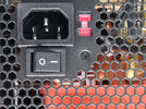
Alright, i say to myself, its either faulty BMS or AMPLIFIER. I check both, nothing, still same problem with new BMS and AMPLIFIER. Then i remember this thing happened once before. So what i do is .. instead of turning the ON switch, i just connect the pins. Guess what, its working normaly. Ok, so i go and measure the button resistance. Its a button from an old pc power suply. I measure while its on OFF and its infinite. I turn it on, voltage of batteries drops from 25V to 1.9V, but the button resistance is 0.4V as it should be (thats what multimeter tells me).

Anyway the fact is, the button breaks the whole thing. The thing is, i cant for the love of god understand how. Its a button. It can either be off or it can be on. But somehow it makes the BMS go nuts and drop the voltage like crazy. Whats more, the batteries that were normaly 4.18V are now sometimes 4.25V. Which is impossible because i just measured them when speaker was off and it was 4.18V.

Anyway, i will replace the button and solve this. But my question is, how the hell can a simple button make this mess ? What ? Does it momentarily jump to high resistance and then back to 0.4 ohm, rapidly, confusing the poor BMS ? The button is on the negative ground line. So when its off, ground connection is cut off.

Again, tried multiple amps, multiple bms ... the only thing that seems to affect it is THIS button. I just tried another button - same type but from different PSU and its working great. Let me stress: (with a deep mystic voice) this has happened once before and same thing, it was solved by another button.
 
A high current switch uses silver plated contacts to carry the high current. But silver tarnishes (turns black) which is a poor conductor then the switch becomes intermittent. Usually a high current switch is used to switch 120VAC (peak voltage is 170V) or 230VAC (peak voltage is 325V) and the high voltage breaks through the tarnish.
 
That would explain it. But i measured the switch and its 0.4 ohms, which seems to be the value all of those switches have. The good ones and the bad one. Strange. Im glad that a switch replacement solved it. Would be happier if i found that out before i wasted time on testing BMS and AMP and all that soldering and repacking work.
 
A switch is never as high as 0.4 ohms. You are probably measuring the resistance of wiring or your meter's leads. My meter's leads measure 0.4 ohms.
Oh, I forgot, was your intermittent button switch from China and sold on ebay?
 
Noooooo. A button was from an old PSU. I recovered like 10 or 15 of them. 2 of them so far had problems. I like the switch because it nicely covers the hole that i make in the wood and it is never perfect. Its really neat cause i make a hole with jigsaw and it fits tightly in and covers the uneven edges to make it look pro. On the down side, its from old PSU's, prolly 15+ years old. From now on i will test every single switch before i assembly the speaker. Opening the speaker and cutting the silicone caulc is not fun. Not to mention unwrapping the battery pack and so on.
 

Attachments

  • Rjbln.jpg
    Rjbln.jpg
    65.6 KB · Views: 169
So the hypothesis is that this button ... while measured 0.4 ohm (measured by my multimeter, i know its not accurate) us actualy very high resistance and that somehow triggers the BMS protection ? I still dont understand how it can do that. U need a big resistance to drop voltage so low that bms protections kick in. Its extremely wierd.

Another question. I have a 2x100W amp and 4 ohm tcp115 which are 45W if i remember correctly. This amp is supposed to put out 100W per channel. I dont have any speakers over 50W so lets say i connect this amp with my tcp115 4 ohm and put the volume to 100%, im gonna burn the speakers right ?


If the answer is yes, i have to say im kind of angry that i couldn't find speakers similar to tcp115 and 100W instead of 45W. I know 100W instead of 50W is only about 25% more but damnit i want that 25%. Even if it was 10% i would want it.
 
The datasheet for the TPA3116 IC shows that it produces 60W per channel into 4 ohm speakers with fairly low distortion when the supply is 24V. To sell more, the Chinese say 100W per channel and do not mention that is with horrible clipping distortion. The heatsink on the Chinese amplifier might be too small for 60W per channel unless a fan is used.
Double the power (+3dB) is only a little louder.
The TCP115-4 is rated at 40W but will survive if you play good music with the amplifier not clipping. Rock music is always at full blast which is bad for a speaker.
Rock music has such high distortion in it that you do not know when your amplifier is clipping.
A continuous tone (or somebody sitting on an organ key?) will quickly destroy a speaker that is made to play real music.
 
Alright i will do some testing. When i make a speaker for myself, i have the privilege that i can do any crazy testing i want and if i burn the speaker i just make a new one. The hardware is cheap enough for that.

But going back to those strange buttons that all seem to measure 0.4 Ohms but u said in reality it is far less than that. I still do not understand how they can be responsible for BMS protection somehow triggering. Even if they were 100 ohms ... how can that trigger BMS protection ?

I am really wondering how this cam happen and i hope u can help me solve this mystery. Some things i noticed:

1) if i short the terminals of the switch with a metal object, i get some sparks. This is probably due to capacitors on amplifier drawing the juice. I am guessing that this big amp surge in combination with button is comehow responsible for bms protection kicking in.

2) this only happens on some of this old pc power suply buttons.

3) whatever is happening, my multimeters are to slow to detect anything. If i measure voltage of batteries at the time of pressing the on button, it barely drops ... for like 0.2V, which isnt nearly enough to trigger any bms protection. If i measure amperage, again, i get like 0.3A at the time of pressing the button. Resistance of the button is 0.4 ohms when i turn it on, but u mentioned already that this is what my multimeter tells me and in reality it is less than that.

Is there any procedure with which i can figure out what is going on ?
 
The resistance of the leads on your multimeter are 0.4 ohms. Short the probes together to see it. You must subtract the resistance of the leads to measure the much lower resistance of a switch. An old switch uses high current silver contacts that turn black (patina) and are resistive until the spark burns off the patina.

The BMS detects too much battery discharge current then disconnects the battery. It also might detect the voltage sag caused by a cheap or old battery.
The amplifier is probably made to use high current lead-acid batteries that do not have a BMS made for a Lithium battery. The amplifier probably has big capacitor that takes a high current to charge. A multimeter cannot measure the very quick voltage drop and high current momentary pulse caused by the capacitor charging quickly.

A power Mosfet can be used in a current-limiting circuit then it applies full power after a short delay for the big capacitor to charge.
 
Status
Not open for further replies.

Latest threads

New Articles From Microcontroller Tips

Back
Top