Continue to Site

Welcome to our site!

Electro Tech is an online community (with over 170,000 members) who enjoy talking about and building electronic circuits, projects and gadgets. To participate you need to register. Registration is free. Click here to register now.

  • Welcome to our site! Electro Tech is an online community (with over 170,000 members) who enjoy talking about and building electronic circuits, projects and gadgets. To participate you need to register. Registration is free. Click here to register now.

DIY bluetooth speaker

Status
Not open for further replies.
It still doesn't explain why BMS cuts off. The cells remain at 4.16V when i turn on the switch. A certain switch never works, a certain switch works some of the times. If i short the wires together it always works. Its as if a switch somehow does something. I just tested 2 other BMS and its the same. I understand what ur saying but i used the same batteries in like 6 speakers and never had a problem. Same bms, same amp, same button, same everything.

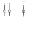
I dont suppose button rated for AC being used in DC is the problem ? The buttons are rated for like 6A at 125V and 8A at 230V. BMS max is 5A 25.2V.
 
Its funny, if i connect wires together, it works. Meaning the problem is in the button. If i connect to a closed switch, it works. If i solder to it and close it, it wont work. I tried soldering to a tiny 2A 100V switch, im guessing its a DC switch since AC is 120V+ usualy. It works with that switch. Then i went soldering to a big AC switch again and the solder kept cracking off. Had to use more flux and a few tries and soldered it on well and now seems to work. We will see for how long.
 
Some switches have severe contacts bouncing when turned on. Oxidation of the contacts worsens the bouncing and maybe the BMS does not like to have bouncing contacts.

Maybe your soldering problem is caused by new lead-free solder instead of the good old solder that has lead in it?
I have never had solder cracking off and I have never used lead-free solder. I never use flux, I use rosin-core solder with a temperature controlled soldering iron. Some soldering irons use a simple adjustable light dimmer circuit so oops it gets too hot when sitting there, oops it gets too cold when soldering. Mine is always at the correct soldering temperature.
 
I will keep on trying to figure out whats going on and will let you know. In the meanwhile i have another question.


I will temporarily be using this little amp as my main computer amp.It's TPA3116 2x50W with big 4 ohm 30W/50W speakers. I have 1 small problem. When my knob is set to 10%, it's already louder than what i usualy listen to. If i set it to 20% it's so loud my neighbours would already protest. I would like some more precision to the knob - i would like to limit the power of the amp/speakers. My goal is so that the loudness of the speakers i now have at 10%, i would have at 20 or 30%. I already reduced voltage of the power suply from 19V to 12V but i am still not happy. Would it be ok if i put some resistors on the speaker wires ? For instance 8 ohm resistor on + wire of the left and right speaker ?
 

Attachments

  • 20220118_172806.jpg
    20220118_172806.jpg
    776.2 KB · Views: 194
A modern audio amplifier has an extremely low output impedance that damps resonances in a speaker. If you add a resistance in series with a speaker to reduce its maximum power then the speaker will resonate like a bongo drum.
Reducing the power supply voltage simply causes clipping to occur at a lower output level.

Our hearing's sensitivity is logarithmic so an amplifier's volume control also should be logarithmic and marked "A" for audio. Maybe the amplifier manufacturer wrongly used a linear volume control that is marked "B"?

The gain of a TPA3116 is set with two external resistors connected to pin 7 and pin 8.
Your photo shows a Wuzhi amplifier with its own IC and its tiny heatsink.
 
No, the one on a picture is indeed the one with TPA3116. There are many Wuzhis, some with chinese chip, some with TPA3116.

But in the meanwhile i figured the problem. It seems that the 3.5mm input is to sensitive In certain sound applications (for instance skype calling sound) i will get distortion. The only way to eliminate it is to lower my pc's output. If i put my pc's volume to 75% or 50%, i completely eliminate the distortion and volume suddenly becomes as expected. This also explains why at amplifiers knob at 15%, speakers scream as if they were at 50%.

So i decided i will put resistors on the signal line going from my pc into an amplifier. Now my question is, do i have to put it on LEFT and RIGHT channel ? Or can i just put it on GROUND line ? This saves me 1 resistor and some work. Also what value of resistor do you recommend. I want to cut half of the strength (to simulate me setting pc's volume to 50%).


Question: Is it ok to put resistor on a GROUND line, or i have to put a resistor on both LEFT POSITIVE and RIGHT POSITIVE ?
 
A logarithmic volume control reduces the level to 10% when turned down to 50% of its rotation
Then if you attenuate the input signal of each channel to 10% you can turn up the volume control to 50% rotation to have the same level as when it was at 10% of rotation without the added attenuation.

The volume control might have its resistance printed on it like "20kA" which is 20k ohms, logarithmic. Then add a 200k resistor in series with each input. The input and amplifier grounds always connect together.
 
But ground is common anyway in 3.5mm jack. I included image to clarify, the square with R is resistor.
 

Attachments

  • wires.png
    wires.png
    15 KB · Views: 190
Ground is the 0V reference, the level the two channel signals are referenced to.
Without a direct connection there, the only thing through the amp is the difference between the left and right channels.
With a high impedance you would still get a bit of the main signal, but the overall sound would be very messed up still; anything near the centre of the stereo image, so equal on both channels, would be faded out to some degree.

Plus any "hum" pickup is no longer connected through ground and cancelled out, so it would be superimposed on the speaker audio.
 
There is no stereo because the speakers on a portable are too close together.

The shields of the input signal wires must be grounded to prevent the shields from picking up interference anyway so each input needs its own series resistor to make separate attenuators.
 
Alright so i put resistors on each line, 150K ohm. It's working quietly as expected and this is GOOD. The problem now is that i get a bit of ground loop buzz that i didnt get before even when i cranked the amp all the way. I just tested it with a separate 3.5mm cable without resistors and the buzz is gone. Its not very loud but i just know its gonna irritate the heck out of me. So is there any way to solve this or will i have to just put the volume of pc to 50% and use 18 ohm resistors in line with speakers like before ?

Edit: whatever i did, i did it wrong. The sound with this gizmo is completely different than the sound using cable without gizmo. Its like high frequencies are cut off or something and its muddy.
 

Attachments

  • 20220119_180219.jpg
    20220119_180219.jpg
    2.8 MB · Views: 188
Last edited:
Edit: whatever i did, i did it wrong. The sound with this gizmo is completely different than the sound using cable without gizmo. Its like high frequencies are cut off or something and its muddy.
Try using two far lower value resistors as a divider, for each channel; eg. a 10K series and 1K to ground.
That should also reduce the hum.

If you are running it from an existing headphone or speaker output, you could use a lot lower still; 1K and 100 Ohm, or 100 Ohm and 22 Ohm?
I'm guessing as you get to a low load, the output level may reduce somewhat, so less attenuation needed..
 
The capacitance of the cable between the attenuator resistors and the new amplifier input are forming a lowpass filter that cuts high audio frequencies. Mount the resistors directly to the amplifier input.

The input cable must be a shielded audio cable with the shield's ground wire from the pc output connector to the new amplifier input. Headphone cables usually are not shielded and will pickup interference buzz and hum.
 
Turns out my amplifier is buzzing extremely loud when no audio input is connected. When i connect audio input, it hums less ... i have to crank volume way up without music to hear it. So for now i have set pc output to like 70% and im also using 18 ohm resistors (with 4 ohm speakers :eek:). This will have to hold for now and in time, i will buy some d-amp box for like 100$. Its still funny that the signal from my DAC is so strong. With my big pioneer amplifier it worked perfect, there was no problem. With this little amplifier.. its like connecting output line into mic line. Its like this 3.5mm on this little amplifier has been made for a lot weaker signal.

Bottom line is, its working ok for now and in time i will buy a new d-amp as i planned. Im kinda missing my old big amp. I was perfectly happy with it, the only reason i sold it is that it was using 35W 24/7, it simply felt stupid having that little furnace on my table in the summer and at the same time underclocking/undervolting my computer to cut electricity costs and make room colder in summer. It will be hard to find cheap d-amp that has the 2 functions i want: big volume knob and a bass knob. Almost nothing under 100$.
 
Is the amplifier playing buzzing from the battery charger? See if the buzzing stops when the battery charger is removed.
If the amplifier plays buzzing when powered only from the battery then the amplifier has a problem if nothing is connected to its input.

The very cheap amplifier might have been made with the wrong value gain-setting resistors causing the gain to be too high and maybe was never tested by Quality Control.

Why and where do you have 18 ohm resistors?
 
Status
Not open for further replies.

Latest threads

New Articles From Microcontroller Tips

Back
Top