Here you go the full schematic.. Some details below..
Short Description:
==============
Idea is to measure a logic high, when ever the input voltage is crossing the set threshold by user. There is a chance that due to capacitance with adjacent cable, there may be an induced voltage at input, which we need to detect and discard..So,
we are loading the input with 1.3A momentarily (Q7 & Q8), if the voltage doesn't decline then we understand its really the source voltage and detecting it as high.
The Input voltage can vary from 0 to 300V. Voltage is detected through R7A & R8A by FPGA (through PWM). Once the FPGA detects a voltage at input, with some delay switching on the load (Mosfet) so the input is loaded with 1.3A for ~100uS.
1. IC7A is PWM for voltage detection going to FPGA.
2. IC2A is PWM from FPGA, to switch ON MOSFET for 1.3A
3. At TP1A I see 6.3 V
4. At TP4A I see 5V
5. 6.3V and 5V raise along with input voltage..(May be with small delay)
Observation:
==========
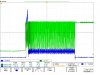
I find lot of oscillations, if the input is connected through a cable (~750uH). If I switch the input using a relay contact, it goes wild due to relay bounce. The requirement is, the input need to be connected through relay.
Question:
=======
1. Why am I getting oscillations, if some thing related to resonance, how can I identify that.
2. Is there any possibility I can avoid this resonance..
3. I cannot have a freewheel diode (as in some coils), because the cable is the source cable which user might use..
4. Due to this high current and voltage together at the same time on the transistor Q2 & Q15, these transistors going bad..(Collector Emitter short, and the high voltage directly dropping across R20A, 21A section, and spoiling the devices there..
Any suggestions would be helpful and would appreciate..