oliverb
Member
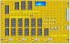
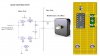
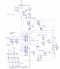
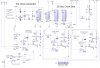
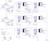
This cct uses 4026B ICs to drive 1.5" 7 Segment LED Displays. Even at 5volts these are quite bright and require no other components to drive.
There are transistor outputs for the following.
30 seconds to drive 30 second Synchronous clocks.
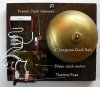
1 hour for hourly electro mechanical chime.
24 hour for possible calendar drive.
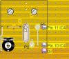
These outputs are controlled by monostables so times can be changed depending on what you want to drive.
Logic is used for clock setting. Seconds can be reset or stopped for precise setting from a time source.
The 30 sec clock pulse can be synchronised with the main display if required (it will then pulse at 00 and 30 secs).
The time is derived from a 32.768Kz quartz crystal.
I have enclosed vero board layouts drawn with LochMaster 3 and cct diagrams drawn with Livewire. I can supply in these formats if required in case you want to mod them for your own use or of course want to make a PCB (the wiring for this project takes a couple of days).
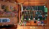
Warning I have designed the vero boards layouts to keep the boards as small as possible this means a lot of wires are crammed into a very small space including both sides of the board.
To fit the cabling in I have used 0.4mm solid wire and have used multiple runs on the Batt & Eth feeds. Not shown on the diagrams are decoupling capacitors of 100nano Farads.
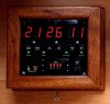
I have not included a layout for the display board as this will depend on the switches and parts of the cct you want to include. I tend to lay the display out depending on what looks best then fit the wiring in around it.
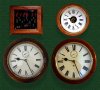
The display lettering is on a second piece of glass set 1mm back from the main glass panel by a rubber spacer (a bit like double glazing).
A full description of this cct can be found here **broken link removed**
Brett.
There are transistor outputs for the following.
30 seconds to drive 30 second Synchronous clocks.
1 hour for hourly electro mechanical chime.
24 hour for possible calendar drive.
These outputs are controlled by monostables so times can be changed depending on what you want to drive.
Logic is used for clock setting. Seconds can be reset or stopped for precise setting from a time source.
The 30 sec clock pulse can be synchronised with the main display if required (it will then pulse at 00 and 30 secs).
The time is derived from a 32.768Kz quartz crystal.
I have enclosed vero board layouts drawn with LochMaster 3 and cct diagrams drawn with Livewire. I can supply in these formats if required in case you want to mod them for your own use or of course want to make a PCB (the wiring for this project takes a couple of days).
Warning I have designed the vero boards layouts to keep the boards as small as possible this means a lot of wires are crammed into a very small space including both sides of the board.
To fit the cabling in I have used 0.4mm solid wire and have used multiple runs on the Batt & Eth feeds. Not shown on the diagrams are decoupling capacitors of 100nano Farads.
I have not included a layout for the display board as this will depend on the switches and parts of the cct you want to include. I tend to lay the display out depending on what looks best then fit the wiring in around it.
The display lettering is on a second piece of glass set 1mm back from the main glass panel by a rubber spacer (a bit like double glazing).
A full description of this cct can be found here **broken link removed**
Brett.
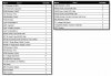
Attachments
Last edited: