Continue to Site

Welcome to our site!

Electro Tech is an online community (with over 170,000 members) who enjoy talking about and building electronic circuits, projects and gadgets. To participate you need to register. Registration is free. Click here to register now.

  • Welcome to our site! Electro Tech is an online community (with over 170,000 members) who enjoy talking about and building electronic circuits, projects and gadgets. To participate you need to register. Registration is free. Click here to register now.

Differential Amplifier

Status
Not open for further replies.

pm4698

New Member
Hello there! I have to design the circuit that is in the attached pdf. I must use a non-inverted differential amplifier (before the integrator). I want the amplifier not to delay my signal(minimum delay) and have large bandwidth. I want to amplify my signal at about 200 times.

Could you suggest a model of amplifier with these features described above?

Thank you in advance
 

Attachments

  • search circuit.pdf
    561.3 KB · Views: 409
Hello there! I have to design the circuit that is in the attached pdf. I must use a non-inverted differential amplifier (before the integrator). I want the amplifier not to delay my signal(minimum delay) and have large bandwidth. I want to amplify my signal at about 200 times.

Could you suggest a model of amplifier with these features described above?

Thank you in advance

hi,
The AD623 is a good intrumentation OPA.

What BW do you define as large.? and what output swing range is required.
 
Basic circuit topology will not work as drawn. Either the first amplifier has to be driven from split supplies +Vs and -Vs (Pins 7 and 4), or the inverting input (pin 2) must be biased to 1/2 of +Vs by adding two more resistors.
 
Your requirements are very ambiguous.

Large bandwidth, how large?

What's the minimum delay?
 
hi pm4698,

I see that you are online, the questions we have asked are very simple, please reply if you want us to help.
 
I am going to use a magnetostrictive delay line (MDL). The coil from the pdf will be placed at one edge of MDL. From the other side i change the magnetic field with another circuit. So, the change of the magnetic field creates a voltage at the coil. The voltage will be at about 50 mVolts.

I want to amplify this voltage without delaying my signal a lot and then use an integrator as a filter.

I do not know mathematics about how to find a minimum desired delay or a maximum desired bandwidth. I was told that the differential amplifier must not delay my signal (minimum delay) and to have large bandwidth. I do not know how much, but the first task is to find an amplifier which inserts the minimum delay and after that i must choose from this category the one with the largest bandwidth.

Do you know any model that would work?Or any maths to calculate the bandwidth and the delay?

Thank you a lot

P.S. I appeared on line before but i was sleeping.Sorry!
 
Last edited:
Can one end of the MDL be grounded (for AC signals), while the signal is amplified single-ended? If so, you do not need a balanced "differential" amplifier. Your schematic is not differential; it is single-ended (unbalanced) as shown.

If the MDL output does require a balanced, differential output, then you should be using an "instrumentation" amplifier.

As I mentioned earlier, the connection shown in your proposed schematic will not work at all, because the inputs to the single-ended amplifier are not correctly biased.

What is the highest frequency (or pulse rise time) that the MDL will pass?
 
My MDL requires a balanced, differential output. In a paper, i read that when the magnetic field changes then a voltage appears at the coil(search coil). It doesn't say something about the voltage at each end of the coil. Just that at the two ends of the coil, i will take 50 mVolts.

The circuit that changes the magnetic field produces a squared pulse from a 555 timer (unbalanced function) with t1=3μsec and T=t1+t2=1msec. So, at the two ends of the coil i will have a similar squared waveform with the same t1 and t2 and width at 50 mV. This signal appears at the two ends of the coil. I do not know exactly the voltage at each end of the coil.

I do not know further information about it and i do not think that at the specific circuit i could ground one end of MDL
 
Last edited:
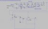
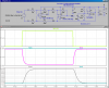
Attached is a simulation. I first tried an LTC Instrumentation amplifier, and it was way too slow. I built a Gain of 50 differential amp using a high-speed LTC opamp. It worked, but it was too slow, too. I then split it into a Gain of 10 Diff amp, followed by a gain of 20 inverting stage, and it works well. I made it so that it operates off a single supply. The rail-splitter (pun intended) is offset to allow for the asymmetric pulse. The floating voltage source at the input simulates what will come out of the delay line, a 3usec wide pulse.

The LT1215 is advertised as a "high-speed" opamp by Linear Technology. I used it in the simulation because LTSpice includes models for all of their products. I tried some slower ones, and they add a lot of delay, and their slew-rate is inadequate. These are pricey, but you will have to use an equally fast opamp if you are going to buy it from someone else.

I suggest you simulate the whole circuit, including the integrator. I have attached the ASC file so you can play with it...

btw- the title says gain of 50, but it is actually a gain of 200.
 

Attachments

  • DelayLine.png
    DelayLine.png
    47.3 KB · Views: 326
  • DelayLine.asc
    3.5 KB · Views: 167
Last edited:
I used the circuit you attached and put 50mV input signal and ton=3μs and Tperiod = 1ms. I designed the integrator and attached it on this circuit and it works just fine and quick (i think). Can you take a look at it?

Thank you a lot!
 

Attachments

  • DelayLine.asc
    4.8 KB · Views: 179
I used the circuit you attached and put 50mV input signal and ton=3μs and Tperiod = 1ms. I designed the integrator and attached it on this circuit and it works just fine and quick (i think). Can you take a look at it?

Thank you a lot!

hi pm.
Just in case Mike is busy, I would suggest you recheck your Integrator circuit.:)

I will leave it to Mike to talk you thru it.:)
 
hi pm.
Just in case Mike is busy, I would suggest you recheck your Integrator circuit.:)

Yes, Eric is right. What you show is a poor low-pass filter, not an integrator.

I don't have time to post more right now. Do some reading and Googling for "opamp integrator" in the meantime.
 
I used the circuit you attached and put 50mV input signal and ton=3μs and Tperiod = 1ms. I designed the integrator and attached it on this circuit and it works just fine and quick (i think). Can you take a look at it?

Thank you a lot!

hi pm,
The ringed areas in the attached drawing need reworking.

I see that you are looking at the Integrator circuit from the datasheet, located bottom right.
 

Attachments

  • AAAimage02.gif
    AAAimage02.gif
    25.2 KB · Views: 217
I corrected some circled areas. I do not understand what's wrong about Vout - area.

From which spot should i take the signal after the 200 gain circuit and lead it to the next circuit (amplifier + integrator)?

P.S. You are right. I used the integrator from that datasheet! Sorry about some questions. I just started playing with this stuff and i do not know much
 

Attachments

  • Untitled-1.jpg
    Untitled-1.jpg
    375.2 KB · Views: 249
I corrected some circled areas. I do not understand what's wrong about Vout - area.

From which spot should i take the signal after the 200 gain circuit and lead it to the next circuit (amplifier + integrator)?

P.S. You are right. I used the integrator from that datasheet! Sorry about some questions. I just started playing with this stuff and i do not know much

hi,
Consider which signal you wish to integrate, the dwg at moment shows the input for the integrator is connected to the positive power rail.!

Why would you want to integrate the power supply voltage.:)

Look at the dwg that Mike has posted, find the point marked Out, this is the signal of interest.

Look at this LTsim of the Integrator section.
 

Attachments

  • AAAimage01.gif
    AAAimage01.gif
    33.2 KB · Views: 209
  • Integrate1.asc
    2.1 KB · Views: 140
Last edited:
hi pm,

The integrator is too slow.

Look at this image.
 

Attachments

  • AAAimage03.gif
    AAAimage03.gif
    25.7 KB · Views: 193
  • Integrate2(2).asc
    2 KB · Views: 143
Last edited:
You are right. I fixed the circuit correctly and it is slow...

Do you suggest any other faster way to stabilize my signal at Vpeak?
 
You are right. I fixed the circuit correctly and it is slow...

Do you suggest any other faster way to stabilize my signal at Vpeak?

hi,
Do you mean you want a peak detector and not an integrator.???

What is the output of the detector connected into.?

EDIT:
Mike's amp work just fine, but the integrator cannot follow.
 

Attachments

  • AAAimage04.gif
    AAAimage04.gif
    30.4 KB · Views: 167
  • Delay_Int3.asc
    5.2 KB · Views: 148
Last edited:
I want to take the amplified squared signal and hold only the peak at the very end of my circuit.

I thought that the integrator would do my job.
 
I want to take the amplified squared signal and hold only the peak at the very end of my circuit.

I thought that the integrator would do my job.


hi,
What is the output of the detector connected into.?

So you want a sample and hold circuit.?

How long do want to hold the signal for.?
 
Last edited:
Status
Not open for further replies.

Latest threads

New Articles From Microcontroller Tips

Back
Top