Continue to Site

Welcome to our site!

Electro Tech is an online community (with over 170,000 members) who enjoy talking about and building electronic circuits, projects and gadgets. To participate you need to register. Registration is free. Click here to register now.

  • Welcome to our site! Electro Tech is an online community (with over 170,000 members) who enjoy talking about and building electronic circuits, projects and gadgets. To participate you need to register. Registration is free. Click here to register now.

Designing a "variable" capacitor ?

Status
Not open for further replies.

slenderglitch

New Member
Hello,
At work I need to design a variable capacitor for a NFC project.
Capacitors are used to tune NFC emitters and receivers. to the right communication frequencies.

I need to design a capacitor which could be variable, customizable without having to desolder, and resolder capacitors.

I've already made a PCB with capacitors and jumpers. Each jumper adds 10pF or 100pF to the total amount of capacitance.
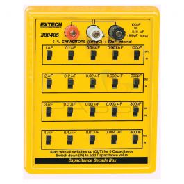
I'd like to have a system like this:
images
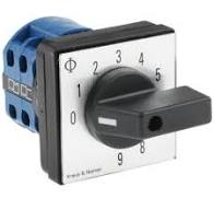
with some predefined capacitance, and I'll just have to change my selection until the antenna is tunned.

If someone have and idea to do this kind of system, thank you!

AJ
 
What is "NFC" ?

JimB
 
Why not just use a variable capacitor from an old medium wave radio. I think their maximum capacity is just over 300 pF. per section and they are normally two section.

Les.
 
Why not just use a variable capacitor from an old medium wave radio. I think their maximum capacity is just over 300 pF. per section and they are normally two section.

Les.

Hello, yes it could be an excellent solution. The problem is that we want to know which value the capacitor delivers in real time.
I had another idea, put some of these variable RF capacitors in parallel and maybe have a little screen that shows the total capacitance value... I think it's possible but I'm also thinking that small capacitance is hard to measure via electronics.

AJ
 
The switch and wiring capacitance will throw off the low values.

Just use a standard air spaced variable cap, and if necessary add a calibrated scale to the knob/dial
eg.

"Switched" units are common - aka a "Capacitor substitution box", but not for very low values due to the inherent stray wiring capacitance.

The capacitance decade box is just a bit expensive for the purpose of my project, but it's a good idea to have precise capacitance values.
So I think I'll use a capacitor like the one you mentionned, and thing Diver300 has mentionned is interesting, I just have to try the variable capacitor on my system, and identify at which angle of the capacitor I have this or that frequency.

Also, do you know if I can measure precisely the capacitance with a classic multimeter?
Coworkers are really busy and you save us a lot of time thank's a lot...
AJ
 
Last edited:
OK, thank you for that.

Now, another question...
What frequency are you intending to use for NFC?

JimB

No problem!
We use generally a sinusoidal signal of 13,56MHz (an electromagnetic field) that is decoded by a (really) little chip on a NFC tag
1628693141622.jpeg

This "antenna" (called tag, whose the thickness is such a sheet of paper) is containing the chip that uses emitter's magnetic field to cross the air.

EDIT: the 13,56MHz is a value imposed by the tag manufacturer, it depends of brands, but generally it's 13,56MHz when you're using NFC.

AJ
 
Thank you, now I understand what it is that you are trying to do.

My first comment is that the switch which you showed in your first post is unsuitable for low level RF use.
Looking at it, it is quite large and is intended for switching fairly high voltages and currents.
The contacts in the switch may not make good contact when driven with low level RF signals.

Also, being a large switch, there will be significant stray capacitance and inductance in the internals of the switch.
As others have commented, a "calibrated" variable capacitor would be a good start.
However, good quality variable capacitors can be a bit difficult to find, and expensive (I don't know how big is your budget?).

For a "quick and dirty" solution, in an experimental environment, I would suggest using D.I.L. switches.
I have used this technique before, switching resistors in parallel with a tuned circuit in an oscillator running around 7 to 8 MHz.
The idea was to measure the effects of resistive loading on the frequency of the oscillator.
It worked quite well.

JimB

Edit
The experiment with the DIL switches was written up here on ETO a number of years ago.
Look here:
to see a picture of the set-up with the DIL switches and a resistor network.
 
Last edited:
Why not just use a variable capacitor from an old medium wave radio. I think their maximum capacity is just over 300 pF. per section and they are normally two section.

Les.

A common value was 365pF, used for MW/LW radios, often with a 176pF built-in (for RF and LO) - although you could buy 300pF or 500pF ones - often used for ATU's etc. by radio hams. 'Back in the day' there was a fairly extensive range, including small ones for VHF etc.
 
Also, do you know if I can measure precisely the capacitance with a classic multimeter?
No chance - as with making a switch box, the lead and other component capacitances will swamp low value external capacitors.
Just moving the meter leads around or holding them will vary it quite a bit..

Some cheap capacitance meters on ebay are quite good; eg. I got one of this style out of curiosity, and it's surprisingly good. It only reads a few pF high at very low values, as long as you connect with minimal wiring:

 
If you use a variable radio capacitor, you could add a vernier dial, such as this, which gives an 8:1 gear reduction to improve the setting resolution.
It also has a dial setting for calibration of the capacitance versus position.

1628705838534.png
 
Why not use a voltage controlled variable capacitance diode?
even more easily available is to use the reverse biased B-C junction of a transistor, which can also act as a varactor, and the capacitance is proportional to the die size, so you can use a power transistor junction for instance if you need something as high as several hundred pF..... for 13Mhz, however something in the range of 20-50pF is more likely.... a 2n2222 will give you a 5-25pF voltage variable capacitor and it's dirt cheap, two of them in parallel, and you have 4-50pF...
 
even more easily available is to use the reverse biased B-C junction of a transistor,
Normal high voltage rectifier diodes work better, as they typically have slow reverse recovery so are less influenced by the instantaneous signal voltage.

A 1N4007 is a good as some expensive HP varicaps. The downside with those or transistor junctions is that each would need individually calibrating.
 
Hello thank everybody for your answers.
I think I understood that:
- using several slide switches will add capacitance to my circuit, so it's not a good solution
- "selectors" as I shown in my first post are too capacitive

Since I have to find a "manual" solution (coworker tell me to use no electronics like rectifier diode or transistor), I think I'll use DIP switches.

EDIT: Unfortunately, it seems that the DIP swtiches can only cop with 100mA or 150mA, and not enough voltage.
I need 500mA and 50V components, I'll search another solution, or adapted DIP switches.

Thank's again!
 
Last edited:
EDIT: Unfortunately, it seems that the DIP swtiches can only cop with 100mA or 150mA, and not enough voltage.
I need 500mA and 50V components, I'll search another solution, or adapted DIP switches.

Could you buffer the dip switches with some kind of transitor; or does that violate the "no electronics" missive?
 
Status
Not open for further replies.

Latest threads

New Articles From Microcontroller Tips

Back
Top