Continue to Site

Welcome to our site!

Electro Tech is an online community (with over 170,000 members) who enjoy talking about and building electronic circuits, projects and gadgets. To participate you need to register. Registration is free. Click here to register now.

  • Welcome to our site! Electro Tech is an online community (with over 170,000 members) who enjoy talking about and building electronic circuits, projects and gadgets. To participate you need to register. Registration is free. Click here to register now.

Design Help --- Bubba Oscillator

Status
Not open for further replies.

ismith1984

New Member
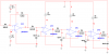
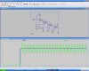
Ok.. I am currently working on a project in which i want to convert a DC signal to AC signal. after much review i decided to go with a bubba oscillator to just obtain a 60 hz signal. my problem is how do i go about using the 12V Dc that i have to obtain that 60hz signal. any helop would be greatly appreciated.
 
thank you brown out for that reply, but I dont think the problem is the connecting the supply. I recently successfully connected my circuit but then after i did so and i ran a trial simulation in Multisim i began oscillating after a few seconds and began amplifying the circuit but never stopped. it appears i might have a problem with my feedback loop and help would be greatly appreciated. also any help in deriving the specific 60 hz frequency given your choice of resistor and capacitor using the information below would be greatly appreciated.

this is the info about the bubba oscillator:
Bubba Oscillator | Free Circuit Diagram
 
The oscillator circuit needs a power supply. Use your 12VDC as its power supply.

But since you did not provide an attachment nor a link to your circuit then we are just guessing that it has a single-polarity power supply.

The Bubba oscillator from Texas Instruments uses a rail-to-rail opamp with a 0.5V bias voltage. Your circuit is probably completely different and maybe uses obsolete parts.
Just guessing since you did not provide enough information.
 
hey guys i am sorry i didnt put more information. i do appreciate you guys responding to my post as your hell is greatly needed and appreciated. anyways i added the multisim file so you guys can let me know where i might be going wrong with this design.
 

Attachments

  • oscillator.zip
    91.9 KB · Views: 866
Your zipped file is bad.
Why don't you post the schematic as a PNG file type?
 
Sorry again guys, it seems i am having more problems providing sufficient information than solving my oscillating problem. anyways i attached both the png file and a pdf file. so i hope this is much better.
 

Attachments

  • bubba_oscillator.pdf
    37.7 KB · Views: 885
  • oscillator.PNG
    oscillator.PNG
    34.4 KB · Views: 3,004
Try 1.5M for R3. Are you telling us that this doesn't work in simulation? Of have you built this?
 
well it is my intention to build it. but it does not work when i ran a simulation on it . i also tried the 1.5M for R3 and that too does not give any result.
 
I got it to simulate correctly in LTSpice. I had to do 3 things to make it work:

1) Correct your VCC connection error in the far-left Amplifier

2) Change your R3 to 2 MEG ohms for sufficient gain

3) Make the 6V a rising edge. Because simulators assume all initial conditions are steady, you need some kind on stimulation to get oscillations started. In a real circuit, these conditions usually exist.
 

Attachments

  • BubbaOsc.JPG
    BubbaOsc.JPG
    130.9 KB · Views: 1,859
hey brownout, thanks for in information you provided, again i appreciate it very much. i corrected the VCC connection problem as well as changed the value of R3. my only concern is the 6V being a rising input. are you telling me i have to make it a square wave input or someting of that sort. and can you elaborate on your explanation a little bit more cause i did not really understand .sorry for the trouble if any.
 
Last edited:
The 6V does not need to be a sqaure wave. You can see in the waveform I posted that it is just a rising edge at 100ms (blue trace) and that it remains a constant 6V after that. All oscillators need something to get them started. In real circuits, that can be a switch on transient, or just random noise. Usually, something is there for starting. I've seen other oscillators that include a starting circuit, but these are rare. If you build this circuit, it will probably start correctly. But in simulations, you might need some kind of transient to make it start. Until now, I haven't simulated an oscillator, so I had to learn that too.
 
hey brownout, i was able to do everything except simulate the rising edge in multisim. i still ran a simulation but it begins to oscillate and then amplified to infinity so my guess is i have to use the exact conditions as you did. any suggestions on how i can make the 6 volts a rising edge on multisim.
 
ok what i mean is, after a few seconds in the simulation it begins oscillating from the DC signal and the amplitude compared to the initial DC signal begins to increase. only it does not stop as in yours amplifying but continues beyond all bounds of the Op amps. it does not cut off at the rails either. it just amplifies to the point that i cannot even see the peaks (negative not positive). any suggestions. i would love to post a picture right now but i am on my MAc Laptop and there is not simulation software on there. as soon as i get home to my desktop computer i will post something. so hopefully my explanation would be less obscure if it is that is.
 
HAHAHA! That's outrageous! You have a serious problem with your simulator. Sorry, I've only used LTSpice. I can't help with other simulators.
 
Last edited:
well i figured i would try it out in PSpice see if it works out to be alright. but multisim is supposed to be one of the better simulation softwares out there so i am really puzzled by this. or i might just have to get a copy of lt spice.
 
These forums show that Multisim does not know if it is coming or going.
It does many things wrong.
 
Hey guys, anyways i tried simulating this thing once more and to no avail in multisim. I tried to build the same circuit in Pspice but i had a DEMO version and it does not allow me to connect as many nodes. I have decided to just run down to radio shack to get the components and just build the stuff. and hopefully if what burnout said to me it will oscillate properly. i do have question about the 2MEG R3 though. should i buy the resistor that will give me a gain of for or do i stick to the two MEG resistor.

another question i have for you guys is, my overall project is to build an inverter and so i decided to use the bubba oscillator as it give me greatest stability with the least distortion given the low frequency output required. i next want to amplify the wave to 120V eventually. do any of you guys have any suggestions in doing so keeping in mind that i want to achieve a pure sine wave output which is very stable and consistent.
 
Status
Not open for further replies.

Latest threads

New Articles From Microcontroller Tips

Back
Top