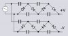
Continue to Site

Welcome to our site!

Electro Tech is an online community (with over 170,000 members) who enjoy talking about and building electronic circuits, projects and gadgets. To participate you need to register. Registration is free. Click here to register now.

  • Welcome to our site! Electro Tech is an online community (with over 170,000 members) who enjoy talking about and building electronic circuits, projects and gadgets. To participate you need to register. Registration is free. Click here to register now.

DC to AC inverter improvents

Status
Not open for further replies.
Hello to everybody :) To begin with, i am trying to built a DC to AC inverter, step up the voltage with transformer at about 500v then use a voltage multiplier to charge some capacitors to about 4kv. I have already built this circuit
12vac-to-220vac-inverter-circuit.jpg
but i have adjusted the cap and resistor for 15khz. I need that high frequency cause my voltage multiplier uses 3kV 10nF ceramic caps. The circuit looks to work well but when i made my on transformer to produce the high voltage, (about 500v) transistors starting to produce some whistling noise and began to heating up even without load. Is this behavior normal to transistors ? I am afraid that they will burned. Can i use mosfets instead of those transistors for better performance ? Also, i have seen that other circuits are using a center taped primary transformer, but i have choose this one in order to keep things simple. Is there any advantage or disadvantage compare to this circuit and a circuit that uses a transformer with a primary center taped coil ?

Thanks :)
 
L1 blocks high frequencies, remove it.
Maybe your transformer is made for 50Hz and is a piece of wire at 15kHz. Use a high frequency transformer.
This circuit uses emitter-folowers with a 3V output voltage loss. Mosfets would increase the voltage loss.
If a center-tapped transformer is used then the transistors can be switches or can be Mosfets with low voltage loss but one side needs to have an added digital inverter stage.
 
Use the transistors just as they are as a pre drive to your mosfets and remove L1. If your 555 frequency is set to the resonant frequency of T1 and C4, then you will see a significant performance increase. You will need to know what the Inductance of T1 is. C4 could be much smaller to accommodate the right frequency paired with the resonant frequency of LC. If it were me I would use a micro controller instead of the 555 only because of better frequency and "dial in" capability and current shoot through prevention techniques. The 555 will work best if the output is a true square wave. Also you might want to diode/capacitor buffer the 555 to minimize any voltage surge issues that could feed into the 555 when the transistors are driven.

May I ask what you end goal is? I have used a 35kV flyback driver (minus the Zener's) limiting the voltage input to 20V with great success .... **broken link removed**

Here is what 35kV can do from a flyback driver of my own design driving a high speed Electrostatic motor and then later a 250kV Marx generator ...
 
Last edited:
Further to beu's comments, it sounds like your trans is saturating, caused by too low inducatce.
You really ought to design the trans properly, however more turns might improve things.
Have you looked at royer oscillators, these are resonant circuits that oscillate at the resonant freq of the trans and its parallel capacitor, and are much more efficient when just thrown together.
 
Thanks to everybody for their reply, really appreciate that. Ok i will remove the L1. I have changed the value of R1=1K, R2=47K, R4 removed and C2=1nF in order to bring the frequency from 50Hz up to about 15kHz. This also kept the duty cycle just slightly over 50%. I did it because my voltage multiplier use 3kV 10nF ceramic caps. I am trying to built an exploding bridge-wire as a project. My capacitor bank is x4 1,3kv 5μF film caps in series for total of 5,2kv and 1,25μF. I only want to charge them at about 4kv for maintenance purposes. I have already built 2x 6 series voltage multiplier according to attached file.

Beau can you pls remake the circuit with the diode/capacitor buffer and the mosfets ? I would really appreciate that. And about micro controller, have got any circuit or something for that purpose ? I am also thinking to make my own transformer for that purpose with a ferrite core, is this goint to work ?

Thanks a lot.


Further to beu's comments, it sounds like your trans is saturating, caused by too low inducatce.
You really ought to design the trans properly, however more turns might improve things.
Have you looked at royer oscillators, these are resonant circuits that oscillate at the resonant freq of the trans and its parallel capacitor, and are much more efficient when just thrown together.


The trasformer i used was a homemade with a ferrite core. The primary had indeed few turns in order to keep voltage high, i guess i have to increase the coil turns. I will try it out.
 

Attachments

  • Stacked Villard Cascade.jpg
    Stacked Villard Cascade.jpg
    24.8 KB · Views: 154
Last edited:
A diode buffer like this will work, just supply th 555 with the output of this ....
https://wiki.analog.com/_media/university/courses/electronics/text/chptr7-f1.png?w=600&tok=d97e78

As far as driving a MOSFET with a 555, two mosfets may not be the way to go since there will be terrible current shoot through possibility. The way you have it might be the best 555 solution since you are using a push pull driver approach.... the key though is going to be driving T1 at the resonant frequency of T1 and C4. 15kHz seems too high for a transformer normally rated for 50/60Hz.... maybe 5kHz but that could be pushing it. You need to determine the inductance of the transformer and know that it will change based on the loading on the output.

As far as the micro, the key to preventing shoot through is to allow one transistor to turn completely OFF before you turn the other one ON. You can do this by either monitoring the voltage or waiting some arbitrary amount of time that allows the transistor to stabilize.

Making your own HV coil can be difficult. Do a search for how other HV transformers are constructed. Typically there are multiple coil stages... each stage may have 100 to 500 turns on it, but there could be as many as 10 stages ... the idea is that each stage can only generate a certain amount of voltage, but because each stage is separated, the voltage isn't enough to break down from stage to stage. With high voltage potential on the outer most stages, you must consider possible alternative high voltage paths, like the core for example... the core becomes fair game as a conductor and precautions must be taken there as well to prevent arcing. Not that you can't DIY and roll your own HV transformer, but HV behaves in ways you might not expect if you are not familiar with HV. In a nutshell, anything that does not conduct electricity essentially becomes a storage device.

There may be OTHER easier ways to generate the voltage you are looking for....

Note: That multiplier looks like a Cockcroft Walton multiplier .... (see video links below) I'll see if I can find the build instructions for the capacitors. I used tranparancy film and adhesive aluminum tape

7kV - Cockcroft Walton multiplier powered from a 12V supply

21kV - Cockcroft Walton multiplier powered from a 12V supply
 
Last edited:
Beau thank you a lot for your reply. I draw a circuit with the buffer diode, just to confirm i am doing it in the right way.
Y8dPVn0.jpg

If it is correct, can you tell me pls also the value of c9 ? Also with a the frequency at 15kz, will just an electrolytic capacitor work or do i have to use a film one ?

Thanks
 
Your schematic shows a Cmos 555. Have you seen on its datasheet its puny output high current that is much less (1/25th) the output current of a bipolar 555?
Your diode has no part number. Use a 1N4148 but not a 1N4001 slow low frequency rectifier.
Why is your value for C8 so high that it passes extremely low frequencies?
Don't you hear the ringing at 15kHz from the transformer like an old TV or are you deaf?
 
The schematic was taken from internet and i just edit it a little bit. The 555 i use is a NE 555 IC, not the ICM7555. Ok i will use a 1N4148 diode for D1. Also the 10.000μF cap was there from the original schematic, i just use a 1.000μF 25v electrolytic capacitor, this cap is ok ?. Also what capacitor i must use for a C9?

I am just now trying to make my own high voltage ferrite transformer that i took from an old PC power supply.
 
The added diode & capacitor should be in the power feed to the 555 oscillator with just the power transistor stage feeding directly from the switch and power source.

The idea is to stabilise the 555 supply voltage so the output stage load current does not affect it.

As drawn, the transistor bases will be permanently "high" once the oscillator starts.

I'd also add an extra capacitor to the power circuit, across the collectors of the two transistors, again to minimise current surges and voltage changes away from the power stage.
 
rjenkinsgb can you saw me into the schematic where to add the capacitors and the diode because i can not understand, my English are not the best.

Thanks
 
The value for C8 and any other coupling capacitor is calculated with the formula 1 divided by 2 x pi x R x f where R is the impedance of the load (your transformer primary) and f is your 15kHz.
Then if the load is 4 ohms the capacitor value is 2.7uF for half the power to the transformer. A capacitance that is about 5 times (13.5uF) will pass almost all of the signal.
 
TEST.jpg


For C9 I would use at least a 470uF.

Follow audioguru's advice for the resonant frequency formula. I can tell you right now 10mF and 15kHz are both way out of range. Find out what the inductance is of that transformer FIRST and work audioguru's formula backwards to find what frequency you should be running the 555 at.
 
I have found a BU808DFI and a K2750 from an old TV. Can i use any of them connecting the base/gate with the TIP41A/TIP42A outputs for more current ? Because my battery Amps are close to 6A while i can only get 1,5A from the transistors.
 
The TIP41 and TIP42 are fairly low current transistors. Why not use transistors that are rated at a much higher current?
Your battery must be tiny if it can supply only 6A. Then the max power from the battery is 12V x 6A= 72W and the circuit losses will result in an output of only about 57W. What do you have that runs from a unregulated squarewave with only 57W? The power will drop as the battery runs down so maybe only 40W.
 
My battery is just x8 AA batteries connected together. Audioguru what do you believe is better, to change the transistors or just put one power mosfet that transistors driving it ?
HWpuunw.jpg


Also what transistors do you recommend for higher current power transistors ?


P.S. I made a transformer that my multi-meter cannot read the output voltage hen i connetc it into my 555 Circuit so i guess the output is more than 600v (max AC Voltage my multi-meter can read) so i tried to make a voltage divider. I found that my multi-meter's internal resistance is 1Mohm so i added one more 1Mohm resistor in series in order to drp the voltage in half but i took only about 10v, little bit weird. So i guess this is because of the small current the secondary coil have, so i just want to try to increase the Amperes to check if the problem will be fixed.

Thanks
 
Last edited:
A battery made with brand new AA alkaline cells will begin at 1A but its 12V will drop to 8V in less than 1 hour. It can never provide 6A to a circuit.
Your circuit with a single Mosfet produces jerking pulses of DC power instead of smooth AC power. AC alternates positive and negative, pulses do not.

Your complementary transistors are emitter-followers that do not need the resistor at their bases.
 
Status
Not open for further replies.

Latest threads

New Articles From Microcontroller Tips

Back
Top