Continue to Site

Welcome to our site!

Electro Tech is an online community (with over 170,000 members) who enjoy talking about and building electronic circuits, projects and gadgets. To participate you need to register. Registration is free. Click here to register now.

  • Welcome to our site! Electro Tech is an online community (with over 170,000 members) who enjoy talking about and building electronic circuits, projects and gadgets. To participate you need to register. Registration is free. Click here to register now.

DC/DC Converter Help

Status
Not open for further replies.
Does the same IPP072N10N3 MOSFET not work for the small MOSFET as well?

I tried just removing the transistor, and this is what I got...
No Small MOSFET.PNG


And in my board, I am using the IPP072N10N3, because I had nothing else...

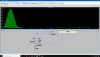
It seems to work perfectly in the simulator, so I guess it is something else that is incorrect??

I measured across the small ohm resistor and got about 30mV...
So I changed it to a 2.9 foot long 22 gauge wire that is supposedly 0.047 ohm, according to this website...

And it still only measures about 30mV across it???

Do I have to apply a load so that the wire heats up and starts acting as a resistor???

Thank you!!!:):D:):):):):)
 
What will this do??
I do not see how it will work the way you wired it.
Normally the Rt/Ct pin only has a RC on it. This sets the frequency and the max duty cycle. This is normal for PWM. Set frequency and variable duty cycle.
When I add a small MOSFET the supply changes to constant off time. The frequency will change with load. I like constant off time style. Most people do not understand how they work. I think they are stable.
 
The current you are seeing at startup is not a function of the PMW. Soft start will not effect this.
Remove most of the parts. Only have C4 input cap, L1 coil, C5 output filter.
In spice the input voltage goes from 0 to 16V in 0nS. (zero time)
C4 charges up.
C5 charges up through L1. The current is a 1/2 sign wave at the resonant frequency of L1 * C5.
This happens with the IC removed. So soft start will not effect this.
119700

I changed V1 to ramp up to 16V in 700uS and the current spike is much smaller. This is more like real world conditions.
 
I really don´t like that overshoot at the start, 5 volts above the target voltage seems a little too much. It looks like your compensation network is not correct.
 
overshoot at the start
The loop response is probably not right. The inductor (inductance) is large. There is no soft start. In SPICE the input voltage goes from 0V to 20V in zero uS. (will not happen in real life) The LC of V2-L1-C3,4 will ring when pounded by the sharp start up voltage in SPICE. This ring might go to a over voltage condition with out the PWM working.
 
I am wanting to protect this circuit from low voltage...
I need a universal solution for low voltage protection that would shut off between 16.1V and 15.5V...

Are there any integrated circuits I would not have to program that would work for a low drain shutoff??
 
16.1V and 15.5V
This circuit uses a TL431 voltage reference. But is uses it as a voltage comparitor and 2.5V referance.
R1 & R2 divide down the VIN voltage to 2.5 volts. Play with the resistor to get the switching point where you want.
The TL431 decides if the voltage is above or below 2.5V.
Q1 pulls "COMP" pin of the PWM to ground. That will force a 0 duty cycle.
119800
 
Status
Not open for further replies.

New Articles From Microcontroller Tips

Back
Top