Continue to Site

Welcome to our site!

Electro Tech is an online community (with over 170,000 members) who enjoy talking about and building electronic circuits, projects and gadgets. To participate you need to register. Registration is free. Click here to register now.

  • Welcome to our site! Electro Tech is an online community (with over 170,000 members) who enjoy talking about and building electronic circuits, projects and gadgets. To participate you need to register. Registration is free. Click here to register now.

dc dc boost converter use TTL494

Status
Not open for further replies.

toandang

New Member
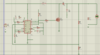
I am designing a dc boost converter as attached, 12V up to 60V.I want to make the simplest circuit but it still works fine. However, it does not work as expected, with no pulsating pulses in pins 8,11. The initial output voltage is 60V and then decreases without any stability. Someone please tell me where i'm wrong ??
 

Attachments

  • Ảnh chụp màn hình (399).png
    Ảnh chụp màn hình (399).png
    44.4 KB · Views: 196
I'd say theres something wrong in the feednack circuit, R6 is very high, and there is no resistor from R6 to the reference.
Also depending on the power your trying to provide the drive to the fet looks oversimple, some kind of active pulldown would make the fet run cooler.
 
I'd say theres something wrong in the feednack circuit, R6 is very high, and there is no resistor from R6 to the reference.
Also depending on the power your trying to provide the drive to the fet looks oversimple, some kind of active pulldown would make the fet run cooler.
I changed the R6 value (51k ohms and some other values) but the problem has not been improved yet.
i don't understand the other idea, i need a circuit to drive to the fet ???
 
something wrong in the feednack circuit, R6 is very high, and there is no resistor from R6 to the reference.
dr pepper is right. Look at the picture below. "5.1k" is missing. The TL494 is a very old and very strange PWM. Most people have not used it. R6 needs to have a high value. It sets the gain at DC.

Also please check your math on R8, R9. You want 60V. The resistors need to divide 60 down to 5V.
1588941844831.png
 
I already knew your schematic provided and tried doing so, but it didn't produce a good result.
I also used R8 and R9 to divide the voltage on pin 1 to 2.5 volts because the voltage on my pin 2 is 2.5 volts (not 5 volts as you said)
 
One potential problem with your circuit is that if the TL494's oscillator stops working the two internal output transistors remain 'off', so Q1 stays 'on' and hence the inductor and/or Q1 gets fried. The addition of a push-pull driver between the TL494 output and Q1 would provide phase inversion and keep Q1 'off' if there were an oscillator fault.
 
Ron, you see it a lot with the Tl494 where vref is divided to 2.5v, dont know why they do that.
The circuit is very minimal, so much so its unreliable.
As alec says the fet quiescent state is on, it would be better to wire the driver transistors in the '494 so that the o/p is high when the fet should be on, then use a pnp transistor to pull down the fet gate to low quickly so's not to have it operating in its linear region long.
But all of this would require a redisgn so I cant really help you further.
 
I see it now the logic on the output is backwards. alec_t & dr pepper are right. Here are some examples.
1588989840615.png
1588989934514.png

1588989971918.png

We really should be using a newer part. UC3843 is a good example. It was built to drive MOSFETs.
 
The bottom example above is what I was thinking about active turn off for the fets, they also cheated taking feedback before the last choke, making compensation easier.
Yep the chip is backwards.
A lot of them were made, I have a pc power supply I ocnverted into adjustable voltage & current.
 
All the examples in #8 are the same.

The TL494 is backwards in every way.
--Most PWM turn on by the clock and turn of at a duty cycle. The 494 turns off at the clock time.
--Most PWM, the feed back goes to the (-) input of a error amplifier. The 494 used (+) input. Non inverting gain that can not go below a gain of one. Making a stable error amp harder.
-- Most PWM, the output of the error amp is high for max power and low for low power. The 494, the output is high for no out put.
-- The 494 was designed to drive transistors not MOSFETs. Back in the early 1980s MOSFETs were not a good choice for power. Other early PWMs; SG1424 in 1976 and MC3420 are pre power MOSFETs.
 
Yes agreed.
The Tl494 did enjoy big success non the less.
Probably because there was nowt else to use at the time.
 
Back in the early 1980s MOSFETs were not a good choice for power. Other early PWMs; SG1424 in 1976 and MC3420 are pre power MOSFETs.

To be fair they never were a good choice - and most SMPSU's used bipolar - occasionally you'd come across ones that used FET's, but they tended to be less reliable and more expensive to repair when they did fail.

Interestingly, a couple of Grundig TV's of the same era used the same 8 pin IC (can't remember the number off hand), but some used an FET and others used bipolar - so I had to keep parts for both in stock. But generally, in domestic electronics at least, FET's were fairly rare - why use a more expensive component when it gives no benefits?, is less reliable, and costs more to repair when it fails?. There was very little difference between the two Grundig circuits, and I alwasy wondered why they did it?.
 
Many of my PWMs power supplies had multiple PWM all running at the same frequency. It is easy to sync most PWM together. In the case of CRT monitors there are periods of time when the display is off and noise from the power supply can not be seen. So the trick is to hide the noise.

I used the TL494 in TV sets and CRT monitors by the 10s of millions/year. In a CRT display the turning on/off of a PWM causes noise in the display. The turn on edge has a small current and can be at zero current. The turn off edge is at high current. All other PWM; the quite turn on edge is fixed by the clock and the noise edge is variable set by the duty cycle. By using the TL494, the quite turn on edge can be anywhere on the display but the large current turn off edge happens with the clock, which is the "flyback time" of the TV set. The noise happens while the CRT is retracing and the video is black. The noise is hidden.

Before the TL494 & SG1424 we built PWMs from op-amps and comparators and transistors. There early parts had problems but were a god sent.
 
a couple of Grundig TV's of the same era used the same 8 pin IC
UC3843/42/44/ etc. When these current mode parts hit the market MOSFETs were getting reliable and the price was headed down. I got prototype parts early, so we had designs ready before the ICs were really available. By the time Motorola, Unitrode and Cherry were in production we were getting all the parts they would allow us. Parts were so limited we helped Samsung to make a clone that was not as good but worked for PC power supplies. I think Samsung was using 10s of millions/month internally.

I have good luck with MOSFETs in power. It takes less engineering to use a FET compared to a bipolar. High voltage/ high current bipolar transistors are hard to find because they are just not used much now. I am playing with SiC and GaN FETs now. The desire to push power supplies into the megahertz has sponged new transistors.
 
Status
Not open for further replies.

Latest threads

New Articles From Microcontroller Tips

Back
Top