Continue to Site

Welcome to our site!

Electro Tech is an online community (with over 170,000 members) who enjoy talking about and building electronic circuits, projects and gadgets. To participate you need to register. Registration is free. Click here to register now.

  • Welcome to our site! Electro Tech is an online community (with over 170,000 members) who enjoy talking about and building electronic circuits, projects and gadgets. To participate you need to register. Registration is free. Click here to register now.

Cutting amperage but not voltage.... Resistor question

Status
Not open for further replies.

iso9001

New Member
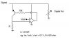
I have this system that sends a signal wire from a controller to a multi-position switch. Every state this switch has run the signal into a resistor, the controller know what state was pressed by reading the voltage of its own signal wire.

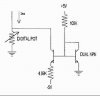
I want to get rid of the switch(es) and use a digital pot to 'simulate' the same thing.

Problem is: The system is setup so that it has 2ma running in that signal wire. My digital pot can handle only a measely 1ma.

I need some way to cut that amperage down (i cant modify the exisiting system) without changing the voltage.


I figured that one way to do this (i'm not certain this will work) would be to place a small 1/4W resistor inline. Since the original resistors are 1/2W i think this will only let 1ma though there.

Am I even close to being right ?
 
you would need to change the value of the resistor to reduce the power flowing through, but then your digital pot would do this wen it changes value
 
The pot is dumb as hell and will gladly ask for more power then it can handel.

If i put a 1/4W resistor inline on the wire somewhere wont that prevent more then 1ma from ever getting to the pot ?
 
Let's go back to basics here: Ohms Law - V = IR

In your case, I is constant (2mA).

By putting a resistor inline, you are going increase the overall resistance, thereby forcing an increase of the signal voltage. Thus, you may get an incorrect reading of the state. Anyway, since you are dealing with a constant current output, you will ALWAYS have 2mA flowing (provided the output doesn't hit the supply rails)

Also, by having a fixed resistor inline, you are changing the zero offset of your switch-position/voltage curve.

The ideal way to solve your problem, is to re-program your system, so it only outputs 1mA. Failing this, maybe there is a solution using a shunt component, though the value of the shunt must be equal to the value of the pot at all times.
 
I can NOT modify the system.

If I put a 10ohm 1/4W resistor in there, and the system is expecting 5V, isnt is going to act like a 5V - 1amp signal ? (I know it would be SLIGHTLY over 5V)

Also, is a 1/4W resistor going to limit the max current in the line ?
 
Any thing that you put in series will raise the voltage at the source, so that won't work. One solution is to put a constant current sink in parallel with the digital pot. This will require a negative voltage in order to work down to ground.
 
right.

If the 1/4W thing didnt work, my plan was to use the pot and make an adjustable voltage sink...


Howver, I have NO IDEA of how to do that :(

Anyone want to stab at it ?
 
Voltage sink?? Not sure what you mean. Anyway, here's a fairly simple current sink for you. Not 100% accurate, due to opamp currents not flowing through "R", but should be good enough for your purposes.

So, if you have 2mA from your signal source, and set it so you have 1mA flowing into the sink, then arithmetically, you have 1mA flowing in your digital pot :p
 

Attachments

  • I-Sink.jpg
    I-Sink.jpg
    6.7 KB · Views: 660
Well.... Thats looks nice although I have NO idea of how thats works :(


I was looking into this awhile ago and someone suggested use of a NPN transistor and an Op amp along with the pot I have to sink a specific voltage

Ie: If i need the existing system to see 2.5V of the 5V in its signal wire I set my voltage sink doodad to -2.5V

Any idea of that they were talking about OR can you explain what your diagram does... (I'm sure I could build it and it would work, BUT i really like to know WHY things i use work, not just that they do)
 
It's a constant current source - it's quite easy to understand how it works from ohms law.

If you have a constant resistance (R), and you keep the voltage across it constant - by simple application of ohms law, the current has to be constant as well.

In this circuit the opamp is used as a comparator, comparing the voltage across R with a reference voltage - if the voltage across R is less than the reference the comparator switches the transistor ON, causing the voltage to increase. If the voltage across R is greater than the reference it will turn the transistor OFF, causing the voltage to decrease.

This action results in a constant voltage across R, which means it has a constant current through it - by changing the value of R, or by altering the reference voltage, you can adjust the constant current drawn by the circuit.

Obviously this requires that the voltage on the emitter of the transistor is always going to be greater than the reference voltage - once it falls below this, the current will no longer be constant. Obviously a low reference voltage would be a good idea.
 
Well, I'm certain thats 100% accurate, but however makes little sense to me since its the circuit in the diagram i still dont undstand, not how ohms law works. I do understand some of it but...

If the op amp is just acting as a comparator why do I need it ? I ALWAYS want the current in the line to be 1ma of the 2.2 it usually is.

I have a pic with a comparator in it, can i just use that instead of the op amp ?

I (think) thats a PNP transistor in the diagram, is it possible to just use that if I dont need the compatator ?

All i want is to use this stupid digital pot without burning it up. It says in its datasheet that I can send 1ma max (although i tested it out and it handled 2ma just fine, prolly not for extrended time though)

Thanks for your help everyone
 
Well, I tried that first diagram, and..... it didnt work :( There is 2.45ma in the signal wire and still 2.45ma on the wiper of my pot. Thats 1.45 too much. Yea, I followed the diagram EXACTLY, used a 741 for the amp, and a PNP transistor.

Thanks Russlk, that does looks great. A few questin though... can you explain a little about how that works and how to adjust the resistors to sink a little more then 1ma (say 1.45 :) )... also, how am I going to come up with -5V ?? (dumb question i'm sure)
 
Un, answered my own question.... it looks like the Vref- is only for the pic's adc to read - voltages correctly. That sucks.

Any super duper easy way to get a -5V ?
 
A charge pump is a good way to get -5V without too much trouble.

To explain phasor's diagram: The opamp doesn't really work like a comparator. The opamp provides feedback control to make sure the current in the resistor below the transistor and therefore the transistor itself is always 1m (set by the voltage on the - terminal). The way I like to think of op amps is they output whatever voltage is nesesary to make their two inputs the same (this rule only works for negative feedback configurations. The transistor works like a negative gain so this is negative feedback even though the feedback goes to the + terminal). So the op amp outputs the correct voltage/current into the transistor base to make the voltage it reads on its + terminal the same as its - terminal. The great thing about feedback is that you don't need to know what voltage and current the op amp is outputting you just need to know that it will output whatever it needs to. The voltage it reads on its + terminal depends on the current flowing into the resistor (no current will flow into the + or - terminals of the op amp - high input impedance). So you set the current the circuit wil draw by setting the voltage on the - terminal.

Hope this helps
Brent
 
iso9001 said:
Any super duper easy way to get a -5V ?

Yes there is. The MAX 1044 and ICL 7660 integrated circuits can act as a charge pump that generates a -5 Volt supply from a +5 Volt supply.

Len
 
iso9001 said:
Well, I tried that first diagram, and..... it didnt work :( There is 2.45ma in the signal wire and still 2.45ma on the wiper of my pot. Thats 1.45 too much. Yea, I followed the diagram EXACTLY, used a 741 for the amp, and a PNP transistor.

Probably, your signal isn't of large enough amplitude to provide a minimum operating voltage for the opamp. Maybe Russlk's idea will work better for you.
 
I really appreiciate all the help.

I think I'm going to need a way to do this without the -5V. I'm trying to keep the final part number down and the maxim deal isnt pdip, and i found some other diagram for 'simple' voltage inverters that are still an extra 10 or so parts.

I'm VERY limited in the parts I can get locally and I really need to get a protoype working soon.

This is so frustrating. I'm thinking so just pushing the whole 2.45ma into the wiper anyway and seeing what happends... I mean, its worked so brief periods in testing... Plus this is not an all the time signal, the signals ground wire only connects to ground every 1/30th of a second. So this thing wont be running 'all' the time. Maybe that'll help, maybe not, i dont know. It'll probally burn up.

Phasor: maybe your right about the opamp, i have it hooked up exactly how the diagram is and it doesnt appear to do anything. arg.

One other thing to condsider: I dont care what the reisitance one the signal wire is. The only thing I care about is that the ADC on the original processor's end sees a 5V signal and then my switches when it needs to.

Actually, I'm starting to think maybe a pot is even way to complicated, I only have 6 resistors to 'simulate' out of the switch I get rid of.... SO.... why dont I just put those resistors hooked upto my pic and just drive the right pin low when a switch is pressed.... that way the signal goes thought a resistor... the pic can handel 2.45ma no problem.... 6 resistors is going to be bigger then i originally wanted to have, but hell.... by the time i get my spi pot and an inverter transistors, and whatnot.... I think i'de much rather waste 6 pins on the pic... I think I'll change my nic here to Dumby McDumbington

Does all that m,ake sense to anyone ?
 
Status
Not open for further replies.

New Articles From Microcontroller Tips

Back
Top