Continue to Site

Welcome to our site!

Electro Tech is an online community (with over 170,000 members) who enjoy talking about and building electronic circuits, projects and gadgets. To participate you need to register. Registration is free. Click here to register now.

  • Welcome to our site! Electro Tech is an online community (with over 170,000 members) who enjoy talking about and building electronic circuits, projects and gadgets. To participate you need to register. Registration is free. Click here to register now.

Best low voltage pulldown resistor

skeeterb

Member
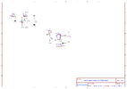
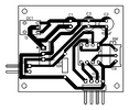
I'm working on my circuit for a simple Traffic Signal decoration. It will have a 12 VDC input voltage and will use a PIC12F510 microcontroller. I have already have the circuit schematic drawn and a PCB layout set up. Since the main voltage of the circuit will be 5 volts, what's the best value to have as a pulldown for the switch input to keep the input from floating when there is no power through the input. I can change the value of the pulldown. As a side note I also have a variable resistor connected to the ADC to adjust the timing for the changing lights. What value is a good one for that as well. I have been using 10K as a default value, but I know that might not be the best. What's your opinion guys?
 
You would have to thoroughly analyze the microcontroller specs, but 10k is a reasonable value for the vast majority of controllers operating at 5V.
Only if your project has tight current draw requirements, a higher value resistor could help. But there are at least half a dozen other circuit changes that would have a larger impact than a pull-down resistor value.
 
A very wide range is perfectly fine, 10K is a good value to use.

Is there any reason you're using a pulldown and not a pullup?, generally pullups are preferred as it removes the 5V rail from the switch, and is thus safer.

Many PIC's also include switchable pullups internally, and using those saves you adding an external resistor.

Likewise, the 12F510 is an old low spec device, you might find the 16F15313 a better option.
 
its only powering different colored LED bulbs, so the current draw will probably be pretty low. It's a traffic light decoration I'm designing from the ground up. The circuit is pretty small, actually. Here's the schematic and the PCB layout.
 

Attachments

  • Schematic_Traffic Light_2023-09-05.png
    Schematic_Traffic Light_2023-09-05.png
    170.4 KB · Views: 95
  • PCB_PCB_Traffic Light_2023-09-05.png
    PCB_PCB_Traffic Light_2023-09-05.png
    8.3 KB · Views: 99
A very wide range is perfectly fine, 10K is a good value to use.

Is there any reason you're using a pulldown and not a pullup?, generally pullups are preferred as it removes the 5V rail from the switch, and is thus safer.

Many PIC's also include switchable pullups internally, and using those saves you adding an external resistor.

Likewise, the 12F510 is an old low spec device, you might find the 16F15313 a better option.
The reason I'm using a pull-down is I'm wanting the pin to remain low until the switch is turned on which. The switch is just a simple toggle that will make the yellow light flash 1 time per second like you see on real traffic lights. The 12F was the first ones I saw when I was looking at the library in EasyEDA. The schematic doesn't actually have the uC on it, just a 8 pin IC socket for when I was designing the PCB. I do look at the data sheets for the uC that I'm using in the circuit. I looked at the 16F15313, and it has a similar enough layout that I don't have to change anything if I do use the 15313.
 
Last edited:
There is no switch (or switch label) on the schematic. Does it connect to H2?

By the way, a much more common reference designator for a header is Px. If the connector is a socket strip rather than a pin header, then use Jx. In this way, the reference designator also tells you the connector gender. I prefer this over labeling all connectors either Px or Jx.

ak
 
The reason I'm using a pull-down is I'm wanting the pin to remain low until the switch is turned on which.

You seem to be missing the point :D

Either way works fine, but generally pullups are used, and you simply detect the pin going low, rather than it going high. It's just a trivial change to the code.

The reason it's done that way, as I mentioned previously, is because using a pulldown means you're feeding the 5V power rail to a remote switch, and that could potentially get shorted to chassis - which might damage things.

Using a pullup means you only have a chassis connection, and an I/O pin going to the remote switch, so shorting to chassis can cause no damage.

Basically it's just good practice, unless there's some specific requirement for it been the other way round?.

The switch is just a simple toggle that will make the yellow light flash 1 time per second like you see on real traffic lights. The 12F was the first ones I saw when I was looking at the library in EasyEDA. The schematic doesn't actually have the uC on it, just a 8 pin IC socket for when I was designing the PCB. I do look at the data sheets for the uC that I'm using in the circuit. I looked at the 16F15313, and it has a similar enough layout that I don't have to change anything if I do use the 15313.

Generally PIC's in the same package tend to have very similar pin layouts - it's normal to be able to swap (most of) them over - there are a few exceptions though.

Over the last few years the 16F15313 has become my 8 pin device of choice - prior to that it was the 12F1840 - and again, the two are interchangeable.
 
I suggest making sure whichever micro you plan to use is available before going too far with you your design and definitely before making a board. A great many chips have been in short supply recently.
 
I was going to use a 16f690 but there was too many unused pins that's why I chose an 8 pin microcontroller
 
I was going to use a 16f690 but there was too many unused pins that's why I chose an 8 pin microcontroller
Often it's a good idea to do development on a larger PIC (such as an 18/20 pin version, and then port it to the smaller device once you have it debugged and working. The extra pins allow you to stick LED's on for debugging, or a serial port etc. - the lack of pins also means that ICSP is problematic.

PIC's are generally fairly compatible with each other, so it's trivial to move it to an 8 pin device once you're ready.
 
The 16F18313 could be a good target device - using the 16F18323 for development, as that has six extra pins.

The 18313 will drop in the upper eight pins of the 14 pin 18323 socket. Other than the extra port, they are pretty much identical and have a lot of useful peripherals, which can be routed to whichever pins you wish using PPS (Peripheral pin select).

They both support in circuit programming and debugging - but with that in use, you only have three pins left on the 18313, against nine on the 18323
 

Latest threads

New Articles From Microcontroller Tips

Back
Top