Yes I understand.
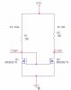
The thing is that i'm talking about having only a single mosfet, driving its gate with a constant voltage from a PSU to get it saturated, and changing its load, hoping to see a constant current for different loads.
I'm afraid that i wont see constant current for the same reason IDS2 was different for each load (while VGS2 remained constant).
So my question is, how do i get the current of a single saturated transistor not to change for different loads?

")