Electro Tech is an online community (with over 170,000 members) who enjoy talking about and building electronic circuits, projects and gadgets. To participate you need to register. Registration is free. Click here to register now.
Welcome to our site! Electro Tech is an online community (with over 170,000 members) who enjoy talking about and building electronic circuits, projects and gadgets. To participate you need to register. Registration is free. Click here to register now.
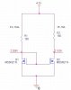
Q2 likely has a slightly higher threshold voltages (Vth) than Q1. Thus a gate voltage of 2.269V causes a current of 24.31mA in Q1 but only 18.7mA in Q2. For the two legs to have identical current, the two transistors would have to be perfectly matched.
Current mirrors work somwhat better with bipolar transistors since the unit-to-unit base voltage match is better between unmatched transistors of the same type.
To do this properly, you need a "matched" transistor pair in a single package. These components are widely available, though I don't have a part number avilable.
To do this properly, you need a "matched" transistor pair in a single package. These components are widely available, though I don't have a part number avilable.
Best you could do without a single package pair is to match to separate devices and bond them face to face with super glue..both will then experience the same rise in temperature( well almost...)
The LED's will determine their own voltage. The fact that they didn't burn up is an indication that at least you are controlling the current, even it it's not identical in both branches of your mirror.
Best you could do without a single package pair is to match to separate devices and bond them face to face with super glue..both will then experience the same rise in temperature( well almost...)
It's working as a current source, it's just that the currents in the two halves aren't matched. The currents don't need to be matched to operate as a current mirror. It still has the high output impedance (that of the Q2's drain) and near constant current of a current source.
It's working as a current source, it's just that the currents in the two halves aren't matched. The currents don't need to be matched to operate as a current mirror. It still has the high output impedance (that of the Q2's drain) and near constant current of a current source.
Yes. The current is inversely proportional to the value of R1. If you want 24.3 mA then reduce the value of R1 by approximately 18.7/24.3 = 77% to 77Ω.
The diode connected transistor acts as a current sinc, and the current is determined by the series resistor. Since resistors can be made to tight tolerances, the current thru the diode connected transistor is tightly controlled. Also, the other half of the pair is a transistor that who's collector current/base-emitter voltage relationship matches the diode connected one, and since the base-emitter voltages are equal in both transistors, the output current is equal, and determined by the series resistor.
Um, no becasue without this connection, the current would not be determined by the resistor. If the connection were not made, you would need a whole other bias arrangement to get any current. Now, you could probably find another bias that works, and would by perfectly legitimate. This is just the bias the current mirror uses. It's simple and effective.
PS: I edtied my post, and I know you're online. You might want to re-read before responding.
This site uses cookies to help personalise content, tailor your experience and to keep you logged in if you register.
By continuing to use this site, you are consenting to our use of cookies.

")