I can do simple. Thank you for the silver platter! (just kidding!) I do appreciate you taking the time to help. I am learning about forums, to me, it has been the same question I posted a couple of months ago. But I realize no one links previous threads and posts. And people respond at various points along the way. Before this thread, I did try to ask how to. Some responses were way over my head, but mostly I grew impatient with the curiosity instead of answers. Enough of that. Trust me, I am less then a novice in electronics. But I can understand and follow your suggestions. Of course I'll be back, talking about switching and commutators and the like. I am sick of monitoring this thing. When I get big enough for my britches and I can actually understand the answers you guys are capable of giving, I will need help on how to build circuitry that senses the rapid rise in current, and automatically shunts,drains,gates,switches etc. the excess current to any where else besides the electrodes. Thanks again. plumber
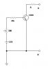
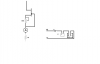
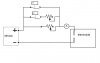
OK, here is a quick draw-up, hope it is easy to follow.
I actually added a second mechanical timer (cheap, can be picked up at hardware store or Walmart possibly for around $10 or so.)
T1 would be the time you want your circuit to have no resistance, the build up time to 1 to 1.5 mA
T2 would be an intermediate timed switch, longer than T1 but shorter than the time of the final process...and includes a series resistance (fixed or a potentiometer). At this point in the sequence, the T2 branch of the circuit will be parallel to the other potentiometer (or fixed resistance). The total resistance will be less than the least of the two. If they are both the same value, say 20kOhm, then the resistance at this point will be 10kOhm.
After T2 opens, you are left with your last potentiometer, in our example we said it was 20k, so we'll go with that.
So you go this sequence...Short, T1 opens (10kOhm circuit), T2 opens (20kOhm circuit)...and 20kOhm for the final duration.
The potentiometer values will be determined to suit your time needs, as will the duration that T1 and T2 are set for.
The three branch idea permits three steps of controlled circuit resistance, and the final resistance will not permit the test to exceed your upper limit. Most likely the final resistance will be near 24kOhm to comply with Ohm's law.
This circuit is "semi-automatic", meaning it isn't a "smart" circuit, as the time and resistance values will take a few tries to get right. It won't be on complete autopilot, but once you have the volume of electrolyte, the battery voltage, and starting electrolyte condition figured out, the process should be repeatable so that you don't neccessarily NEED precise feedback type control.
") I keep expecting some one to say "why didnt you just say so! Here's how!" Thanks again plumber
I keep expecting some one to say "why didnt you just say so! Here's how!" Thanks again plumber