Electro Tech is an online community (with over 170,000 members) who enjoy talking about and building electronic circuits, projects and gadgets. To participate you need to register. Registration is free. Click here to register now.
Welcome to our site! Electro Tech is an online community (with over 170,000 members) who enjoy talking about and building electronic circuits, projects and gadgets. To participate you need to register. Registration is free. Click here to register now.
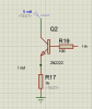
If the input voltage is 2.5V then the emitter voltage is about 1.85V.
1.85V/1k (the emitter resistor)= 1.85mA. The base current is also in the emitter resistor so its total current is 1.85mA + (1.85mA/100)= 1.8685mA.
If the transistor hFE is 100 then the base current is 1.85mA/100= 18.5uA.
depending on post 1 and 3
what this configuration equations ? while the desired output current is emitter current using for relay-on because the current from mcu insufficient
depending on post 1 and 3
what this configuration equations ? while the desired output current is emitter current using for relay-on because the current from mcu insufficient
It's a VERY poor way to feed a relay - you should put the relay in the collector of the transistor, so it works as a switch, giving the maximum possible voltage to the relay, and the minimum loss in the transistor - putting it in the emitter uses the transistor in an analogue mode, greatly increasing losses.
The relay coil should be connected from the collector of the transistor to +5V and a reverse connected diode should be parallel to the relay coil to quench its inductive high voltage spike. Then the transistor should have its emitter connected to 0V and have a series base resistor calculated for a current that is 1/10th the collector current.
The relay coil should be connected from the collector of the transistor to +5V and a reverse connected diode should be parallel to the relay coil to quench its inductive high voltage spike. Then the transistor should have its emitter connected to 0V and have a series base resistor calculated for a current that is 1/10th the collector current.
but i connect relay to the emitter and it work very well !
i just want this configuration equations ? while the desired output current is emitter current using for relay-on because the current from mcu insufficient
If the loaded output of the MCU is 3.5V and the base-emitter voltage drop of the transistor is 0.7V then the 5V relay coil gets only 3.5V - 0.7V= 2.8V which might not be enough to reliably activate the relay. Maybe your relay worked very well today but might not work tomorrow.
If the relay coil is at the collector then it gets about 4.9V even when the output voltage from the MCU is lower than you think.
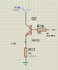
please this my final structure
i need it for another work (not for relay)
i need this circuit analysis and equations , because i don't understand the previous explain very well
Unless the application is known ("another work" is not known) there is no way to help you with that circuit. Why do you insist on placing the resistor (load) in the emitter? You were told to place the load (resistor in the collector circuit and told why to do it that way.
hFE of a transistor is the current gain or amplification factor of a transistor.
hFE (which is also referred to as β) is the factor by which the base current is amplified which is fed into the transistor.
A transistor works by feeding a base current into the base of the transistor. The base current is then amplified by hFE to yield its amplified current. The formula is below:
IC= hFEIB=βIB
So if 1mA is fed into the base of a transistor and it has a hFE of 100, the collector current will be 100mA.
Every transistor has its own unique hFE. The hFE is normally seen to be a constant value, normally around 10 to 500, but it may change slightly with temperature and with changes in collector-to-emitter voltage.
Check the transistor's datasheet for the hFE value in its specifications.
This is what Audio Guru is trying to tell you when he says:
The relay coil should be connected from the collector of the transistor to +5V and a reverse connected diode should be parallel to the relay coil to quench its inductive high voltage spike. Then the transistor should have its emitter connected to 0V and have a series base resistor calculated for a current that is 1/10th the collector current.
Your transistor in your "final structure" is called an emitter follower. Its emitter does not switch the 1k load on and off. Its emitter voltage is about 0.7V LESS than its base voltage. Its base voltage might be only 3.5V so its emitter will be only 2.8V.
For a transistor to be used as a switch then the emitter is connected to 0V and the load is connected to the positive supply. Then the transistor circuit is called common emitter. Even if the base voltage is fairly low the collector switches the load from the positive supply to very close to 0V.
The output current of a common-emitter transistor that is properly turned on is simply the supply voltage divided by the load resistance, minus its saturation voltage that is typically 0.1V (shown on the datasheet of a 2N4401 with a 100mA collector current).
The datasheet of any little transistor shows that for it to be saturated (properly turned on) then its base current should be 1/10th its collector current.
Vb is NEVER 3.5V (I worded it wrongly). The voltage fed to its series base resistor can be from about about 1V to many volts. The output voltage from a 5V MCU drops to maybe 3.5v when it is loaded.
another question ...
if i have a circuit its output is DC change in range of ( 0,2.5v) ,Vcc =5 volt
but there are a small ripple
what cause this ripple ?
if i put a capacitor between output and GND (Low pass filter) is solve the problem ?
there is a standard value for this capacitor ?
Ripple might be caused by using an unregulated AC-DC wall wart. The capacitor should be placed from its positive terminal to its 0V terminal. The value of the capacitor depends on the amount of ripple, how low you want the ripple to be and the load current.
Many circuits (like an opamp) perform wrong and might over-heat if a capacitor is placed from their output to ground.
the voltage path from opamp to voltage divider then to ADC (MCU)
the MCU input is that DC rippled voltage .
is the capacitor has an effect on opamp perfor ?
Are you talking about your ohm-meter circuit? Its schematic does not show where the resistor to be measured is connected.
The input wiring or messy wires on a solderless breadboard might be picking up mains hum. Use a shielded audio cable for the input wires and use a compact pcb.
Since the output of the opamp feeds a voltage divider made with two 1k resistors then simply filter the output of the voltage divider with a capacitor to ground.
This site uses cookies to help personalise content, tailor your experience and to keep you logged in if you register.
By continuing to use this site, you are consenting to our use of cookies.