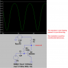
Because, once you have turned on the transistor, you don't have to overcome the junction-drop and the transistor will "diode detect" the signal. All the diode does is prevent the voltage on the capacitor (say 10n) from leaking back to the low impedance of the tuned circuit.
Continue to Site