Electro Tech is an online community (with over 170,000 members) who enjoy talking about and building electronic circuits, projects and gadgets. To participate you need to register. Registration is free. Click here to register now.
Welcome to our site! Electro Tech is an online community (with over 170,000 members) who enjoy talking about and building electronic circuits, projects and gadgets. To participate you need to register. Registration is free. Click here to register now.
sorry about that im in a hurry....im gonna use switches rather than LDR...what kind of switches can i use in the circuit you gave to me?....thanks a lot...
sorry about that im in a hurry....im gonna use switches rather than LDR...what kind of switches can i use in the circuit you gave to me?....thanks a lot...
thanks mate! tomorrow i'll buy a normally open, push to close switches .. D i hope it will work tomorrow .. thanks for all your help mate .. thanks! really appreciate that ..
thanks mate! tomorrow i'll buy a normally open, push to close switches .. D i hope it will work tomorrow .. thanks for all your help mate .. thanks! really appreciate that ..
mate i already measure the volts in the up button it start to 5 and when i push the button it goes down to zero .. but still it doesn't count .. what should i do next ??
mate i already measure the volts in the up button it start to 5 and when i push the button it goes down to zero .. but still it doesn't count .. what should i do next ??
the up button is the only button i put in the breadboard to test the circuit , i didn't put for the mean time the down and clear button should i put that already ?? .. i measure 2 volts and when i push the up button it goes down to zero ..
the up button is the only button i put in the breadboard to test the circuit , i didn't put for the mean time the down and clear button should i put that already ?? .. i measure 2 volts and when i push the up button it goes down to zero ..
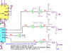
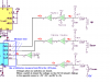
For the counter to work all the components shown on that drawing post # 46, must be connected.
Look at this drawing and measure the voltages marked in blue, inside the blue box, tell me what on each of the 4 pins.
This site uses cookies to help personalise content, tailor your experience and to keep you logged in if you register.
By continuing to use this site, you are consenting to our use of cookies.
D thanks mate ..

")
")