Styx
Active Member
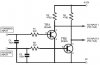
Lets go back to your topology:
I appreciate that you have only One PIC PIN (the PWM pin) BUT in your figure you have 2 signals comming from the PIC.
PWM
You have a "PWM Pulse" and a "PIC Input" I take it by "PIC input" it is actually an output from the PIC?
So you do have at lest 2 pins available?
Right Now you are saying you are using "PIC Input" as some form of H-Bridge direction signal? and the "PWM Pulse" as your driving pulse?
PIC Input LOW
With "PIC Input" LOW The no matter what the "PWM Pulse" signal does no current will flow
PIC Input HIGH
With "PIC Input" HIGH there is a problem. With PWM Pulse LOW: There is no path for current to flow around the supply - ok BUT you have both top FET's ON!!! Zero-loop across the motor, that ok.
BUT you are also supplying gate voltage to the bottom FET's They are now ON!!!! the only saving grase is there is no close-path for the supply current to flow
However, When PWM Pulse is fired and thus turning on the lower FET you now are A 5 FET's on and effectivley a short across the supply
I fail to see how this is ever expected to work, upless I am missing soming
The only way this would work is IF each side "PIC Input" was their own signal, complement of each other which from what you are saying they dont.
Please If I am mis-understanding how you are driving this please correct me, it is my week off and I am just spending the week getting drunk watch DVD's. But I have seen no H-bridge topology where it is driven like that. You always need the complement PWM
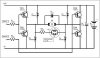
Thus what I am saying is scrap the bottom FET, this now gives you TWO PIC output pins. feed one of these signals to the left input and the other to the right. The difference between the two signals is that they are the complement of each other.
50% duty => Net current = 0
>50% duty => Net current >0
<50% duty => Net current <0
Scrap your bottom FET and your circuit should work. Use mine and you have the benefit of dedicated gate-drive and tuneable shoot-though protection.
I appreciate that you have only One PIC PIN (the PWM pin) BUT in your figure you have 2 signals comming from the PIC.
PWM
You have a "PWM Pulse" and a "PIC Input" I take it by "PIC input" it is actually an output from the PIC?
So you do have at lest 2 pins available?
Right Now you are saying you are using "PIC Input" as some form of H-Bridge direction signal? and the "PWM Pulse" as your driving pulse?
PIC Input LOW
With "PIC Input" LOW The no matter what the "PWM Pulse" signal does no current will flow
PIC Input HIGH
With "PIC Input" HIGH there is a problem. With PWM Pulse LOW: There is no path for current to flow around the supply - ok BUT you have both top FET's ON!!! Zero-loop across the motor, that ok.
BUT you are also supplying gate voltage to the bottom FET's They are now ON!!!! the only saving grase is there is no close-path for the supply current to flow
However, When PWM Pulse is fired and thus turning on the lower FET you now are A 5 FET's on and effectivley a short across the supply
I fail to see how this is ever expected to work, upless I am missing soming
The only way this would work is IF each side "PIC Input" was their own signal, complement of each other which from what you are saying they dont.
Please If I am mis-understanding how you are driving this please correct me, it is my week off and I am just spending the week getting drunk watch DVD's. But I have seen no H-bridge topology where it is driven like that. You always need the complement PWM
Thus what I am saying is scrap the bottom FET, this now gives you TWO PIC output pins. feed one of these signals to the left input and the other to the right. The difference between the two signals is that they are the complement of each other.
50% duty => Net current = 0
>50% duty => Net current >0
<50% duty => Net current <0
Scrap your bottom FET and your circuit should work. Use mine and you have the benefit of dedicated gate-drive and tuneable shoot-though protection.