Continue to Site

Welcome to our site!

Electro Tech is an online community (with over 170,000 members) who enjoy talking about and building electronic circuits, projects and gadgets. To participate you need to register. Registration is free. Click here to register now.

  • Welcome to our site! Electro Tech is an online community (with over 170,000 members) who enjoy talking about and building electronic circuits, projects and gadgets. To participate you need to register. Registration is free. Click here to register now.

Cordless tool Li-Ion upgrade - lots of pictures.

Status
Not open for further replies.

Nigel Goodwin

Super Moderator
Most Helpful Member
OK, I've got a collection of cordless power tools that use the same batteries - but they are now 11 years old, and the batteries (I have three batteries, and two chargers) are now pretty useless, as you would expect. The tools themselves are perfectly fine.

The batteries are 18V 2AH and use NiMh half-C cells, with the input/output connector spot welded to the top of the batteries themselves.

Batt1.png


These are the batteries removed from the casing, the thin brown and black wires got to a diode (I presume it's a diode) as a temperature sensor.

Batt1.png


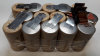
I was considering ordering some replacement half_C cells, but 45 of them is a lot of money, and they still aren't very good batteries. So as I've got a pile of 'rescued' 18650 Li-Ion cells I decided to use those (we replace a LOT of batteries at work, both when they are faulty, and as regular service work on request - so I have a decent supply of them - I can't bear to see them thrown away!). For the 18V I needed 5 cells, and I hoped to be able to squeeze 10 in to double the power - but it was a little tight, so I keep with 5 instead (which incidentally is exactly what our new DeWalt drill at work uses).

So using our battery spot-welder I built them up in a pack of five cells, and ordered some suitable battery protection boards from China.

Batt4.png


This is a completed battery pack, the black wire you can see is the temperature sensor from the protection board, which is glued to the side of the pack. Plenty of hot melt glue holds everything together.

Batt7.png


Next was the problem of connections, so I used more hot melt to fasten the original connector in place in the top, and ran thickish wires from that.

Batt9.png


The new battery pack was hot melt glued in the old case.

Batt8.png


And the wires from the top soldered in place, to the sides of the metal clips you can see above on the protection board.

Batt10.png

So that's the batteries done - next job will be to rebuild the chargers - these use a conventional mains transformer, and an LM324 quad opamp for the charge controller - the new pack has separate charge+ and output+ from the protection board, so I connected the middle pin (used for the original temperature sensor) to the charge+ connection.

I've got some small Chinese charger boards, adjustable constant voltage and constant current, so I'm planning using those, and probably a PIC to monitor charge status - I haven't really decided yet, and I've yet to try charging the packs 'manually' to see what the protection board does as regarded charging (I pre-charged all the cells before building the packs).

Incidentally, the old batteries weighed 1056gm, the new ones only weigh 486gm, so less than half the weight.

Nice little upgrade, the batteries were free, and the protection boards under £2 each.
 

Attachments

  • Batt2.png
    Batt2.png
    902.5 KB · Views: 147
Last edited:
Hi Nigel,
Last Sunday Lidl had some Li-Ion batteries and chargers on offer at a good price. They are no longer being shown on their website. They were listed as 20 volts but they will be the same as what is normally 18 volt. They have 2 Ah and 4 Ah versions of the battery. Last time they had them on offer I bought two of the 2 Ah ones and made and adaptor plate to fix them to the old nicad battery case from the old cordless drill.

Les.
 
I've been thinking about doing this for a while. Interesting, thanks ;)
 
I have an old AEG EZ506 and it's charger that I've been wanting to convert to Li-ion for a while so this is good to see.
 
Hello,

My only question would be just how the pack behaves when you go to put a tough screw into the wall. I tested one of my older NiMH drills and found it to draw more then 30 amps, which means that is at the top end of some of the best single Li-ion cells on the market in the package size 18650. Thus, i have to wonder what the protection circuit is rated for and also what the cells are rated for. If you draw too much current from a low rated cell it could be very bad. Intermittent use comes to mind, but then i would want to do good testing first.

I would also think the number of cells in series has a lot to do with it, because that dictates the voltage and the voltage has to match the drill. With a low voltage drill like 9v i would think it would draw more current than an 18v drill, but then the manufacturer has control over this and control over what cells they use in the pack and if they use any in parallel.

So it would be interesting to find out if the protection circuit cuts out when trying to put screws into the wall into dense 2x4 studs for example.
 
Hello,

My only question would be just how the pack behaves when you go to put a tough screw into the wall. I tested one of my older NiMH drills and found it to draw more then 30 amps, which means that is at the top end of some of the best single Li-ion cells on the market in the package size 18650. Thus, i have to wonder what the protection circuit is rated for and also what the cells are rated for. If you draw too much current from a low rated cell it could be very bad. Intermittent use comes to mind, but then i would want to do good testing first.

This is the board I used, I specifically looked for one designed for cordless drill use - it's rated at 20A continuous.

https://www.aliexpress.com/item/5S-...ard-Protection-Circuit-Board/32877030450.html

I've not had occasion to use it yet, but it looks pretty good.
 
This is the board I used, I specifically looked for one designed for cordless drill use - it's rated at 20A continuous.

https://www.aliexpress.com/item/5S-...ard-Protection-Circuit-Board/32877030450.html

I've not had occasion to use it yet, but it looks pretty good.


Hello again,

Oh 20 amp isnt bad that's for sure, but i do know my older drill took 30 amps or more stall current and when putting in screws sometimes it can stall or just draw nearly that current. I took care to measure it so i would know what diode i would need in series to drop some voltage when using it with a slightly higher voltage battery.
That was a 9.6v drill, so maybe the higher voltage ones dont draw as much but i never measured my new one.
So maybe you could try putting some screws in and see if you can get it to almost stall. See if it shuts down or not.
 
Hi Guys

I've just completed a similar project starting from the opposite direction.

I'm a great fan of the cordless multitool, in particular the Dremel variant - I find them to be excellent for small detail drilling, cutting and sanding. However, they have a significant drawback in the battery charger. The battery block comprises 2 sets of 3 700mAh 1.2v AA NiCD batteries connected in series with spot welded tags, offering either 3.6v or 7.2v depending on the position of the switch.

The charger however, is a problem, taking up to 5 hours to fully charge a unit and no protection if it remains powered after a full charge is achieved. I started out with 3 batteries and 3 chargers but managed to 'cook' first one, then two of the chargers by forgetting the time and leaving them powered. Then a couple of weeks ago, inevitably, I did the third one !

Since I don't have your expertise in designing my own circuit, I search the net and found a scheme to charge NiCD batteries using a CC/CV circuit and a Peak Detect' system that impressed me. Apparently, NiCD batteries once fully charged and subject to a temperature rise lose a little voltage, as as little as 7mV perhaps, but this circuit detects that voltage change and uses it to turn off the charge circuit.

I subsequently built two of these chargers, mounted side by side and just in case the peak detect doesn't work, I added a PIC controlled timer which can be adjusted to cut the power to the charger after a set time between 5 mins and 5 hours.

This is the finished charger unit ..

Out Case 1.JPG


.. .. .. .. note the old Dremel Charger case, butchered with a hacksaw to provide a suitable battery mount;

.. .. and this is the circuit board .. .. ..

PCB 1.JPG


.. .. .. .. the 'spaghetti' seen disappearing off to the left is connected to a pair of timer tripped relays.

I have run this charger several times now and the peak detect protection seems to work very well.

As some of you will recall, I'm very much a novice and the validity of the peak detect idea, apart from working, is over my head but the principle was checked by another expert ETO member and proved to be accurate and correct. I've no idea if a similar principle would apply to NiMh batteries, but it might be worth a look.

I would like to acknowledge the intellectual copyright of the circuit to Mr BH Abbot of New Zealand.

Bientot

S
 
Very nice work, MM :) I wish all my builds were so tidy!
Can you supply a link to the design?
 
Hi Guys

I've just completed a similar project starting from the opposite direction.

I'm a great fan of the cordless multitool, in particular the Dremel variant - I find them to be excellent for small detail drilling, cutting and sanding. However, they have a significant drawback in the battery charger. The battery block comprises 2 sets of 3 700mAh 1.2v AA NiCD batteries connected in series with spot welded tags, offering either 3.6v or 7.2v depending on the position of the switch.

The charger however, is a problem, taking up to 5 hours to fully charge a unit and no protection if it remains powered after a full charge is achieved. I started out with 3 batteries and 3 chargers but managed to 'cook' first one, then two of the chargers by forgetting the time and leaving them powered. Then a couple of weeks ago, inevitably, I did the third one !

Since I don't have your expertise in designing my own circuit, I search the net and found a scheme to charge NiCD batteries using a CC/CV circuit and a Peak Detect' system that impressed me. Apparently, NiCD batteries once fully charged and subject to a temperature rise lose a little voltage, as as little as 7mV perhaps, but this circuit detects that voltage change and uses it to turn off the charge circuit.

I subsequently built two of these chargers, mounted side by side and just in case the peak detect doesn't work, I added a PIC controlled timer which can be adjusted to cut the power to the charger after a set time between 5 mins and 5 hours.

This is the finished charger unit ..

View attachment 114320

.. .. .. .. note the old Dremel Charger case, butchered with a hacksaw to provide a suitable battery mount;

.. .. and this is the circuit board .. .. ..

View attachment 114321

.. .. .. .. the 'spaghetti' seen disappearing off to the left is connected to a pair of timer tripped relays.

I have run this charger several times now and the peak detect protection seems to work very well.

As some of you will recall, I'm very much a novice and the validity of the peak detect idea, apart from working, is over my head but the principle was checked by another expert ETO member and proved to be accurate and correct. I've no idea if a similar principle would apply to NiMh batteries, but it might be worth a look.

I would like to acknowledge the intellectual copyright of the circuit to Mr BH Abbot of New Zealand.

Bientot

S


Hi,

Pretty nice, and quite ambitious.

Yes the "minus delta V" technique is one of the main end-of-charge detection schemes. There are times it can fail though such as when the battery gets old so they always include a back up method like maximum time which i think you covered. There is also teh temperature rise method which measures the temperature rise above ambient and turns off when the rise is too much.
The minus delta V is also less for come batteries than for others so for some it is harder to detect, but the higher the charge current the higher the delta V when it gets fully charged.

I have a cheap Harbor Freight "Dremel' knockoff that works to some degree but not much power. The charger is a SLOW charger too.
 
Hi Guys

The design for the charger is here **broken link removed** or here http://www.bhabbott.net.nz/

The timer is a standard PIC based timer I've used for several projects from Picprojects.org .. I think he's a member here.

I was very surprised and a bit horrified when I first opened a failed Dremel charger and saw what was contained .. .. .. .

Dremel Remains.JPG


.. .. .. .a bit of a stark contrast !
All new tech to me, but so far very effective in operation.

Edit

I've just discovered the Precision Timer is no longer on the Pic Projects webpage .. schematic.pdf below

S
 

Attachments

  • Precision Timer Schematic.pdf
    26.8 KB · Views: 153
Last edited:

Splashed out on the buttons didn't you?, they are pretty expensive (we use them at work, and I used one on my IR Remote Tester project long ago).

Incidentally, I was going to use the same button on one of our new products - then I found it was too easily pressed by accident (as we found once the first protype was built), as the button part protrudes considerably. After lot's of searching, I found a suitable button switch from the same manufacturer that is larger and has a more recessed button.
 
Splashed out on the buttons didn't you?

LOL .. .. I'm not actually sure where I got those buttons from, I have quite a few in a box.

We do have a Sunday Market nearby with a guy who sells lots of electronic bits, new & 2nd hand .. he also has what he calls 'Goody Boxes' at £10 each the contents of which vary from odd components I don't ever recognise to whole bags of caps, resistors etc., .. they may well have come from there.

S
 

These are cheap. I can't find the order I picked a while ago, but this is just the first listing I found on Ali:
https://www.aliexpress.com/item/Mom...n-Switch-10pcs-red-10pcs-black/681794061.html

I found them a little annoying as there is some resistance to pushing them and the rubbery feel. I would just put them on something that required a firm press and wasn't pressed very often. Good to know that they aren't recessed.
 
Status
Not open for further replies.

Latest threads

New Articles From Microcontroller Tips

Back
Top