Continue to Site

Welcome to our site!

Electro Tech is an online community (with over 170,000 members) who enjoy talking about and building electronic circuits, projects and gadgets. To participate you need to register. Registration is free. Click here to register now.

  • Welcome to our site! Electro Tech is an online community (with over 170,000 members) who enjoy talking about and building electronic circuits, projects and gadgets. To participate you need to register. Registration is free. Click here to register now.

Cool projects to do

Status
Not open for further replies.
You can find lots of interesting projects on www.instructables.com, many of which are beginner-level. You'll even find some content there from me! (same username)
 
A flip flop is basically a latch logic gate. Apply a pulse to the S(set) input, and the output will be latched on, regardless of what happens with the input to the S input.

Apply a pulse to R(reset) and the output will be latched off.

Flip Flop Basics
 
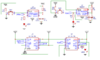
A JK flip flop is one of the variants of clocked or synchronous style bistable.

An SR bistable (aka flip flop) in not synchronous, it switches state as soon as either a set or reset signal is present.

The simplest clocked one is a D type; the output (Q) is set to match the D (Data) input only when the clock input changes from low to high.
Connect the inverse output /Q (not Q) to teh D and it will change state each time the clock changes to high, dividing the clock frequency by two.
Connect two or more Q out to D in, and clock them together, you get a shift register.

A JK bistable has two control inputs and extra logic included. If both are low, nothing happens when it is clocked. If J is high and K is low, Q is set high when the clock occurs; J low and K high, Q is set low when clocked. Connect Q to J and /Q to K and again you get a shift register.

Set both J and K high, and it alternates (divide by two) at each clock.

Most D or JK etc. type have reset and often set inputs as well, that force an immediate state change, like SR.
Those are most often used as part of a power-on-reset sequence so everything starts in a defined state, but can be used in other ways.

This video may be helpful:
 
Huh, I didn't think J-K had a clock input. Learn something every day.
Daniel, you can make a S-R flip-flop (the simplest kind) by connecting two of the gates in a 74HC00 together. 1 input from each gate gives you the S and R inputs, the outputs form the Q and not-Q outputs, you just wire the output of each one to the remaining input of the other one to make it into a flip-flop.
 
I think the point is being missed here. A flip flop has plenty of applications. There's been a lot of explaining about different types of flip flops, without any explanation of the why.

Flip flops are handy if you need one, but a flip flop on its own isn't a cool project.
 
Not cool I agree, but it's an experiment to try. I can still remember the magic of doing exactly that one myself many years ago. Even though I'd read it's truth table and explanation and thought I knew what to expect, it was still magic.
 
Is your solar charge controller the infamous Micro M+? I never sourced it or built it, but I plan to build it for use with my auto battery collection, using free energy from the sun.
 
Is your solar charge controller the infamous Micro M+? I never sourced it or built it, but I plan to build it for use with my auto battery collection, using free energy from the sun.

don't think its infamous
 
Ola ... Hmmm how to explain ... A flip flop is a type of temporary memory storage IC ... There are 3 common types: D, SR, JK ... The outputs of these devices can change states depending on what you set on the input and how the device is clocked (please search "<insert flip flop name> truth table" on the web to see what I'm trying to say) ... They can either be negatively or positively clocked ... Negative clock signal = signal that goes from on to off and positive clock signal = signal that goes from off to on ... 555 timer will come in handy for clocking signal because it eliminates something called bouncing when using mechanical switches or pushbuttons ... I found a great book on the web called "Digital Fundamentals" by Thomas L. Floyd ... It will explain it in a much better way so please try to download it ... Attached below is an application of a D Type FLip Flop to form a serial in serial out shift register that I had to do for school. YouTube Channel "Ben Eater" has the best tutorials on digital systems so check him out as well
 

Attachments

  • IMG_20201206_195317.jpg
    IMG_20201206_195317.jpg
    1.7 MB · Views: 198
  • Schematic_Digital Systems 1B - Practical 3.png
    Schematic_Digital Systems 1B - Practical 3.png
    20.2 KB · Views: 194
Last edited:
Status
Not open for further replies.

Latest threads

New Articles From Microcontroller Tips

Back
Top