Electro Tech is an online community (with over 170,000 members) who enjoy talking about and building electronic circuits, projects and gadgets. To participate you need to register. Registration is free. Click here to register now.
Welcome to our site! Electro Tech is an online community (with over 170,000 members) who enjoy talking about and building electronic circuits, projects and gadgets. To participate you need to register. Registration is free. Click here to register now.
I'm trying to convert a Microcontroller PWM signal at 0-3.3vpk to +/-12v. I'm sure it could be done with an optoisolator. Does anyone know the 'correct' way to do this. It must be able to reach -12v so a rail to rail op-amp isn't enough. Any help would be invaluable.
Why won't a rail-to-rail opamp do? A CMOS opamp output would get very close to the supply rails. Or you could use almost any opamp with a ±13V supply .
What supplies do you have and how close to -12V does the output really need to be?
I only have a clean +/-12v supply and it really does need to be able to reach -12v to within 0.1v. Other parts of my circuit use the ADA4610-4 rail to rail op-amp but I'm afraid I can't seem to find the figure for how close it gets to the rail. I know it will be one transistor drop away but I'd imagine that's more than 0.1v. Link to datasheet if it helps https://www.analog.com/media/en/technical-documentation/data-sheets/ADA4610-1_4610-2_4610-4.pdf.
And thanks so much
Ahh it seems they get within a couple of mV so I think I'll go with this circuit which give me reasonable noise of 17mV. I'm glad i can use an op-amp thanks for your help.
Unless you can see a way of doing this to get a cleaner signal with the same number of stages.
You could use the 3.3V signal to drive a half-bridge (that is connected between +/-12V with a floating gate driver circuit for the high-side FET ). It would have more components than just the op-amp though but has higher power capability should you need it.
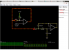
Forget the LPF for a moment. The basic gain/offset stage has some problems. Where are you going to get a 1.8V reference? Second, the gain R2/R1 is too high, causing you to saturate the output of U2. See V(a). Is that what you intended?
Note that to expose the saturation at U2, I temporarily made the supply voltages +-13V!
It's intended to control a voltage-controlled-filter. I made the gain a little too high to ensure I reach -12v. The reference was most likely going to be a trimpot divider between 3.3 and 0v.
In an ideal world I'd like a circuit that could output -12v when the PWM duty cycle is 0% sitting at 0v and only go high when PWM is active. This would avoid having to have an accurate centrepoint.
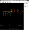
Here is a version with the gain/offset stage with different values, and a different method of getting the offset. I tweaked your filter values a bit, too.
This shows another problem. If the PWM duty cycle is small, the slew rate of the amplifier prevents it going from rail to rail, and the "filtered" average will not be what you think it should be...
Have you identified an opamp which can accept a ±12V supply and give a clean ±12V output at 50kHz? I couldn't find a suitable opamp model in the LTspice library to simulate those conditions.
Well I'm pretty new to circuit simulation. I was aiming for 100uS rise time so the output could oscillate at around 5KHz but this isn't entirely necessary as long as it can function above 500-1000Hz.
The modifications Mike suggested work well on my primitive simulator but I'm struggling to find accurate models for my op-amp.
The ADA4610 has a typical rise time of 21 V/us so can I assume this will be fine?
On my original circuit I neglected to show there was a one-pole RC with a 7KHz cutoff prior to the op-amp.
So with Mike's modification this is where I'm at.
I'm using this basic circuit simulator just to get and understanding as it's quicker than Qucs for someone like me (all generic parts).
Have you identified an opamp which can accept a ±12V supply and give a clean ±12V output at 50kHz? I couldn't find a suitable opamp model in the LTspice library to simulate those conditions.
I cheat, and use the "idealized" universal opamp model that LTSpice has in-built. Note you can easily tweak its parameters (like GBP or SlewRate) to match those of some "real" opamp you can buy.
Do you happen to know offhand of any RRO ones which can take 24V between the rails, Mike? Nearly all the LTspice models seem to be for either low voltage (5V or so, or unspecified) and fast, or higher voltage and sluggish. I think tweaking those models would lead to unrealistic sims.
Oh sorry I meant the PWM, is at 50KHz to be above well above audio frequencies. I'd like to be able to get up to 20KHz out post filtering on the +/12v signal but I assume I'd need more filter poles to achieve this without it being audible in the signal path so I've set the cutoff to around 8KHz
I start out making the circuit work with the ideal model, then I see what I can buy, and modify the parameters as appropriate. For example, in this case an LT1499 would do ok. It's slew rate is a bit slower than 10MV/sec, but otherwise it is RRIO and capable of operating on +-18V.
Here is another approach. It also distorts the PWM duty-cycle a bit, but at least it stops at +-12V, with good rise-fall times.
Oh fantastic Mike. I knew there'd be a way to do this using MOSFETs. This is exactly what I was looking for. There's 8 of these in the final application so I was aiming for the lowest part count whilst maintaining low-noise. Really appreciate yours and alecs help.
I started out doing what Mike did in #17. (active pull down)
Then I tried this.
V4 should be set to 3.3V for DC analysis.
For AC analysis it needs to be set to 0V.
R7 & R8 = 20k to 3.3V/2.
Gain is set by R4 & R5.
Remove U1. Just for fum.
Frequency response with 17db gain. and compare to sample RC filter. Keep the ratio of C1/C2. Change value to get the frequency you want.
Wrong OP-Amp. Just pick one at random. The +/- 12V could be +/- 15V unregulated. If you don't want to use R-R amp.
This site uses cookies to help personalise content, tailor your experience and to keep you logged in if you register.
By continuing to use this site, you are consenting to our use of cookies.

 . 40-50KHz and maximum 1mA current for the output signal.
") .
. 


 .
.