Continue to Site

Welcome to our site!

Electro Tech is an online community (with over 170,000 members) who enjoy talking about and building electronic circuits, projects and gadgets. To participate you need to register. Registration is free. Click here to register now.

  • Welcome to our site! Electro Tech is an online community (with over 170,000 members) who enjoy talking about and building electronic circuits, projects and gadgets. To participate you need to register. Registration is free. Click here to register now.

Controlling the speed of DC motor using a PC

Status
Not open for further replies.

tommyflynn

New Member
Hi,

I am looking for help with the wiring involved with controlling the speed of a motor on LabVIEW through a PC rather than changing it manually on my motor control card. I currently have the motor running in both CW and ACW directions using LabVIEW.

I know I must desolder the potentiometers on my motor control card (How I currently can control motor speed) and connect this to my NI myRIO device. I feel I know how to configure the LabVIEW code (slider/dial output) but require some help with the wiring.

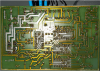
I have attached a couple of photos.

1579532045965.png
1579532152458.png
 
What are the part-number/specs/connections of that motor-control board?

- The motor control board is used to control a 24V DC Motor.
- The 1k Piher Spain carbon potentiometers have 3 connections each, the inner part is rotated either CW/ACW to increase/decrease speed.
- There are 10 ports (1-10) on the board itself.

Unfortunately I do not have a part number for the board itself.
 
Without knowing exactly where the pots are in the circuit you cannot simply substitute an external signal.

The motor control board almost certainly has the facility for an external speed control setpoint - but you need to known the board specifications for that as well.

Can you post a good close-up photo of the board - both sides? If no one can find it, at leas we may be able to trace the connections to the presets & terminals.

That green plastic base is a standard sectional part - jut pull the ends and it will separate somewhere so you can take the board out.
It will clip back together again when you replace the board in it.


ps. It's not a good idea to use brown & blue wire for low voltage devices, someone may think it's 220/240V AC...
 
There is a few circuits out there for converting a digital signal to a analogue to drive the motor controller, it is popular for VFD's etc where the input is 0-10vdc etc.
Max
 
Not enough information has been furnished. Does that row of input-pins have one called a 'speed setpoint' or somesuch?
Where did you get the controller?
 
The 1k Piher Spain carbon potentiometers have 3 connections each, the inner part is rotated either CW/ACW to increase/decrease speed.
That is where it begins. Just as a suggestion you can use a DMM and measure across each pot, then measure one side of pot to center wiper and other end of pot to center wiper. Do this as you rotate the pot through its range. If you get a varying voltage like 0 to 5 volts or 0 to 10 volts that could make for a good start. Less havig a drawing of the controller it;s pretty much guess.

Ron
 
1579694084528.png

Underside of Motor Control Board, I have drawn red lines indicating the potentiometers.

Thanks.
 

Attachments

  • 1579693566309.png
    1579693566309.png
    1.5 MB · Views: 228
You appear to be in luck!
The pots are ground referenced, via a resistor at the "low" end.

Terminal 2, where you have the negative of the 24V supply is also signal ground.

The "input point" looks to be the two joints between the pots, where the cathodes of the two diodes connect.

It appears to select which pot is in use by feeding power to the top of one or the other, so only one passes a voltage through those diodes.

Turn both presets to minimum speed and you should be able to feed an external voltage to that point to set a speed.
The voltage required will be trial and error - it could be 10V for full speed or it may only be 3V for full speed; you will need to experiment with that.
 
That covers it. :)

Ron
 
Status
Not open for further replies.

Latest threads

New Articles From Microcontroller Tips

Back
Top