Continue to Site

Welcome to our site!

Electro Tech is an online community (with over 170,000 members) who enjoy talking about and building electronic circuits, projects and gadgets. To participate you need to register. Registration is free. Click here to register now.

  • Welcome to our site! Electro Tech is an online community (with over 170,000 members) who enjoy talking about and building electronic circuits, projects and gadgets. To participate you need to register. Registration is free. Click here to register now.

Controlling Multi Steppers With TPICB595 Shift Register

Status
Not open for further replies.

R74

New Member
Hi,

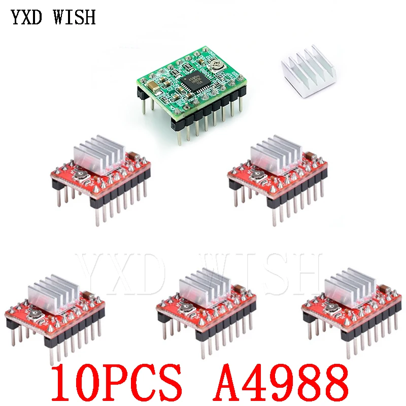
I need to control 16 Nema 17 steppers :
4 wires / 2 Phase, Voltage: 12 V, Current: 0.7 A / Phase
All steppers must be controlled individually and may run all together.
Would like to know if a TPIC6B595 is the correct choice for this project.
If not, Please give me a suggestion.
Thank You.
 
That can only handle 150mA per output and is open drain output, so not suitable.

You need two full H-bridge power stages per motor, for four wire motors. You would need six or eight wire motors that have coils that are or can be configured as centre-tapped to use just open collector / open drain type drivers.

What MCU do you intend to use?
And, what speeds must the motors run at; do they microstepping or need to coordinate movement at different speeds, eg. as in contouring like with a 3D printer or CNC?

You could use just shift registers (plus power output drivers of some sort), as long as the MCU can calculate all the new positions fast enough and update either 32 or 64 bits of output data at the required rate, either for direct phase control with ballast resistors or PWM.

For precise positioning (interpolating between steps) you need PWM with current feedback for each motor or phase.

Ideally, use a dedicated stepper driver for each motor, such as an A4988. That allows you to just provide a direction control and give step pulses when required to each unit, in real time, plus a few control signals that could be updated when required by such as a separate set of shift register outputs.

The overall requirements very much depend on the exact application.
 
Thank you for your kind reply.
Actually, the final goal is to make something similar to this complex project, but in a much smaller scale.
I saw a discussion on this subject on the Arduino forum where someone had made PCB boards with the TPIC6B595 that could control 48 steppers( 28BYJ48).
Those cheap steppers use plastic gears and IMHO are not the correct choice. So, I was wondering how to use better steppers.
To make things much easier, maybe one can always start from home position, by stalling the steppers, then perform a pattern and home again.
Have not decided on the MCU yet, but I don't think an Arduino can handle this.
 
Nice!
The original steppers (28BYJ48) have centre tapped coils, so are rather simpler to drive than the NEMA17 four wire ones.


You can get unipolar (six wire) in NEMA17 sizes, which reduce the complexity a bit, but the motors require current limiting regardless of drive type - either a ballast resistor to limit the maximum current (which uses a lot of power and dissipates a lot of heat), or current control at the driver. Making drivers will be relatively expensive either way.

I think your best option is to use four wire motors and mass produced modules to drive each motor; A4988 based ones are available for less than $1 each in tens.
eg.

Those should be the same pinout as these, which have rather more details in the listing:

As with the first diagram on that page, everything can be fixed wiring for each motor and power, with the modules just needing two unique logic signals each for step and direction (and the logic ground connection).

That means you could control four motors from a normal logic-level eight bit shift register such as a 74HC595, and chain as many of those as you want to control multiple sets of motors on one SPI output from an MCU.

With SPI running at eg. 10MBit, the update time would be only just over 3uS for 32 bits, four cascaded registers controlling 16 motors total..
You would need two updates for each step stage, one to set the step bits high and another to set them low; still under 10uS.
In each sequence, only set the step bits for the motors that have to move at that instant.

The whole thing could easily run at 1000 updates per second with plenty of time between output sequences to do the pattern move speed calculations as to which motors require a move and when.


For an MCU, I'd suggest an ARM based arduino compatible board such as an M0. Using SPI as the main outputs, you don't need many I/O pins.

eg. These are cheap, program with the Arduino IDE once you add the seeed library files, have SPI that can run at 12Mbit I believe, with 256K Flash and 32K RAM:

Or with WiFi included:
 
You are GREAT ! Thank you.
I'll order some of these, do some testing and get back to you.
 
Sorry, I'm a newbie.
Do the MCUs you indicated run on 3 or 5 volts ? I couldn't find the answer on the Internet.
If they run on 3v then the shift register would run at 5Mhz max ?
Would that mean I have to consider half frequency rate and double update time ?

Thank you.
 
Those both work from 5V input, with onboard regulators and the MCU IC operating at 3.3V
The shift registers can run from the 5V supply.

You may need to use level converters if the shift register inputs do not operate at the 3.3V output level of the IC.
Or use 74HCT595 rather than HC? Those are TTL level compatible so will happily work from 3.3V input levels.
 
Status
Not open for further replies.

Latest threads

New Articles From Microcontroller Tips

Back
Top