Hi - I'm involved with a project to design and devlop a fully autonomous hovering platform as part of a 4th year engineering group project.
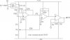
I am dealing with the sensors, more specifically rate gyros. I am feeding the output from these gyros into a differential amp which outputs a +ve or -ve dc voltage dependant on +ve or -ve rotation. this signal then goes into an integrator which integrates the rate to give a angle of rotation. This signal is then fed through a non-inverting amplifier to bump up the signal to give +-5V for +-20 degrees rotation of the platform. The problem I have is that the output signal is drifting too much and I can't control it well enough. The strange thing is that I have managed to get the the output from the integrator to have negligible drift over minutes and also, the amplifier only has a gain of 24 (not massive eh...). I know it is pretty difficult to see without a circuit diag but has anyone got any ideas??.....I am not the best at electronic design as my degree is in Engineering and Management......thanks in advance.
Glenn Stevens")
I am dealing with the sensors, more specifically rate gyros. I am feeding the output from these gyros into a differential amp which outputs a +ve or -ve dc voltage dependant on +ve or -ve rotation. this signal then goes into an integrator which integrates the rate to give a angle of rotation. This signal is then fed through a non-inverting amplifier to bump up the signal to give +-5V for +-20 degrees rotation of the platform. The problem I have is that the output signal is drifting too much and I can't control it well enough. The strange thing is that I have managed to get the the output from the integrator to have negligible drift over minutes and also, the amplifier only has a gain of 24 (not massive eh...). I know it is pretty difficult to see without a circuit diag but has anyone got any ideas??.....I am not the best at electronic design as my degree is in Engineering and Management......thanks in advance.
Glenn Stevens