Continue to Site
Follow along with the video below to see how to install our site as a web app on your home screen.
Note: This feature may not be available in some browsers.
	LIST	p=16F628		;tell assembler what chip we are using
	include "P16F628.inc"		;include the defaults for the chip
	ERRORLEVEL	0,	-302	;suppress bank selection messages
	__config 0x3D18			;sets the configuration settings (oscillator type etc.)


		cblock	0x20			;start of general purpose registers
			count			;used in looping routines
			count1			;used in delay routine
			counta			;used in delay routine
			countb			;used in delay routine
			tmp1			;temporary storage
			tmp2
			templcd			;temp store for 4 bit mode
			templcd2
			Acc

		endc

LCD_PORT	Equ	PORTA
LCD_TRIS	Equ	TRISA
LCD_RS		Equ	0x04			;LCD handshake lines
LCD_RW		Equ	0x06
LCD_E		Equ	0x07

		org	0x0000
		goto	Start

Main_Text	addwf	PCL, f
		retlw	'S'
		retlw	'T'
		retlw	'A'
		retlw	'R'
		retlw	'T'
		retlw	'I'
		retlw	'N'
		retlw	'G'
		retlw	0x00

Text_wire		addwf	PCL, f
		retlw	'W'
		retlw	'i'
		retlw	'r'
		retlw	'e'
		retlw	' '
		retlw	0x00

Text_pass	addwf PCL, f
		retlw	'P'
		retlw	'A'
		retlw	'S'
		retlw	'S'
		retlw	0x00

Text_fail	addwf PCL, f
		retlw	'F'
		retlw	'A'
		retlw	'I'
		retlw	'L'
		retlw	0x00

Start		movlw	0x07
		movwf	CMCON			;turn comparators off (make it like a 16F84)

Initialise	clrf	count
		clrf	PORTA
		clrf	PORTB
		clrf	Acc
;		clrf	NumL
;		clrf	NumH


SetPorts	bsf 	STATUS,		RP0	;select bank 1
		movlw	b'00010000'			;PORT A for LCD
		movwf	LCD_TRIS
		movlw	b'10000000'			;PORT B for Decoder
		movwf	TRISB
		bcf 	STATUS,		RP0	;select bank 0

		call	LCD_Init		;setup LCD
		Call	Delay255

		clrf	count			;set counter register to zero
Main	movf	count, w		;put counter value in W
		call	Main_Text			;get a character from the text table
		xorlw	0x00			;is it a zero?
		btfsc	STATUS, Z
		goto	Sub_Main
		call	LCD_Char
		incf	count, f
		goto	Main

Sub_Main	Call	Delay255
			btfss	PORTA, 4
			Goto	Sub_Main
			Call 	Delay255
			movlw	b'01001000'
			movwf	PORTB
			Call	Repeat
			Call 	Delay255
			movlw	b'01010000'
			movwf	PORTB
			Call	Repeat
			Call 	Delay255
			movlw	b'01011000'
			movwf	PORTB
			Call	Repeat
			Call 	Delay255
			movlw	b'01100000'
			movwf	PORTB
			Call	Repeat
			Call 	Delay255
			movlw	b'01101000'
			movwf	PORTB
			Call 	Delay255
			Call	Repeat
			movlw	b'01110000'
			movwf	PORTB
			Call	Repeat
			Call 	Delay255
			movlw	b'01111000'
			movwf	PORTB
			Call	Repeat
			Call 	Delay255
			movlw	b'00001000'
			movwf	PORTB
			Call	Repeat
			Call 	Delay255
			movlw	b'00010000'
			movwf	PORTB
			Call	Repeat
			Call 	Delay255
			movlw	b'00011000'
			movwf	PORTB
			Call	Repeat
			Call 	Delay255
			movlw	b'00100000'
			movwf	PORTB
			Call	Repeat
			Call 	Delay255
			movlw	b'00101000'
			movwf	PORTB
			Call	Repeat
			Call 	Delay255
			movlw	b'00110000'
			movwf	PORTB
			Call	Repeat
			Call 	Delay255
			movlw	b'00111000'
			movwf	PORTB
			Call	Repeat
			Call 	Delay255
			Goto	Start

Repeat		bsf		PORTB, 0
			Call	Check
			Call    Delay255
			bcf		PORTB, 0
			bsf		PORTB, 1
			Call	Check
			Call    Delay255
			bsf		PORTB, 0
			Call	Check
			Call    Delay255
			bcf		PORTB, 0
			bcf		PORTB, 1
			bsf		PORTB, 2
			Call	Check
			Call    Delay255
			bsf		PORTB, 0
			Call	Check
			Call    Delay255
			bcf		PORTB, 0
			bsf		PORTB, 1
			Call	Check
			Call    Delay255
			bsf		PORTB, 0
			Call	Check
			Call    Delay255
			Return

Check		Call	LCD_Clr
			Call	Delay255
			clrf	count			;set counter register to zero
Check_Sub		movf	count, w		;put counter value in W
			call	Text_wire			;get a character from the text table
			xorlw	0x00			;is it a zero?
			btfsc	STATUS, Z
			goto	Check_main
			call	LCD_Char
			incf	count, f
			goto	Check_Sub

Check_main		Call	Delay255
			movlw	5
			Call	LCD_Line1W
			Incf	Acc, w
			btfsc	Acc, 7
			Goto	Start
			btfsc	PORTB, 7
			Goto	Pass
			Goto	Fail
Ret			Return

Pass		Call 	Delay255
			Call	LCD_CharD
			Call	LCD_Line2
			clrf	count			;set counter register to zero
Pass_Sub	movf	count, w
			Call	Text_pass		;get a character from the text table
			xorlw	0x00			;is it a zero?
			btfsc	STATUS, Z
			goto	Ret
			call	LCD_Char
			incf	count, f
			goto	Pass_Sub

Fail		Call 	Delay255
			Call	LCD_CharD
			Call	LCD_Line2
			clrf	count			;set counter register to zero
Fail_Sub	movf	count, w
			Call	Text_fail		;get a character from the text table
			xorlw	0x00			;is it a zero?
			btfsc	STATUS, Z
			goto	Ret
			call	LCD_Char
			incf	count, f
			goto	Fail_Sub

;Subroutines and text tables

;LCD routines

;Initialise LCD
LCD_Init call 	LCD_Busy		;wait for LCD to settle

		movlw	0x20			;Set 4 bit mode
		call	LCD_Cmd

		movlw	0x28			;Set display shift
		call	LCD_Cmd

		movlw	0x06			;Set display character mode
		call	LCD_Cmd

		movlw	0x0c			;Set display on/off and cursor command
		call	LCD_Cmd			;Set cursor off

		call	LCD_Clr			;clear display

		retlw	0x00

; command set routine
LCD_Cmd		movwf	templcd
		swapf	templcd,	w	;send upper nibble
		andlw	0x0f			;clear upper 4 bits of W
		movwf	LCD_PORT
		bcf	LCD_PORT, LCD_RS	;RS line to 0
		call	Pulse_e			;Pulse the E line high

		movf	templcd,	w	;send lower nibble
		andlw	0x0f			;clear upper 4 bits of W
		movwf	LCD_PORT
		bcf	LCD_PORT, LCD_RS	;RS line to 0
		call	Pulse_e			;Pulse the E line high
		call 	LCD_Busy
		retlw	0x00

LCD_CharD	addlw	0x30			;add 0x30 to convert to ASCII
LCD_Char	movwf	templcd
		swapf	templcd,	w	;send upper nibble
		andlw	0x0f			;clear upper 4 bits of W
		movwf	LCD_PORT
		bsf	LCD_PORT, LCD_RS	;RS line to 1
		call	Pulse_e			;Pulse the E line high

		movf	templcd,	w	;send lower nibble
		andlw	0x0f			;clear upper 4 bits of W
		movwf	LCD_PORT
		bsf	LCD_PORT, LCD_RS	;RS line to 1
		call	Pulse_e			;Pulse the E line high
		call 	LCD_Busy
		retlw	0x00

LCD_Line1	movlw	0x80			;move to 1st row, first column
		call	LCD_Cmd
		retlw	0x00

LCD_Line2	movlw	0xc0			;move to 2nd row, first column
		call	LCD_Cmd
		retlw	0x00

LCD_Line1W	addlw	0x80			;move to 1st row, column W
		call	LCD_Cmd
		retlw	0x00

LCD_Line2W	addlw	0xc0			;move to 2nd row, column W
		call	LCD_Cmd
		retlw	0x00

LCD_CurOn	movlw	0x0d			;Set display on/off and cursor command
		call	LCD_Cmd
		retlw	0x00

LCD_CurOff	movlw	0x0c			;Set display on/off and cursor command
		call	LCD_Cmd
		retlw	0x00

LCD_Clr		movlw	0x01			;Clear display
		call	LCD_Cmd
		retlw	0x00

Delay255	movlw	0xff			;delay 255 mS
		goto	d0
Delay100	movlw	d'100'			;delay 100mS
		goto	d0
Delay50		movlw	d'50'			;delay 50mS
		goto	d0
Delay20		movlw	d'20'			;delay 20mS
		goto	d0
Delay5		movlw	0x05			;delay 5.000 ms (4 MHz clock)
d0		movwf	count1
d1		movlw	0xC7			;delay 1mS
		movwf	counta
		movlw	0x01
		movwf	countb
Delay_0
		decfsz	counta, f
		goto	$+2
		decfsz	countb, f
		goto	Delay_0

		decfsz	count1	,f
		goto	d1
		retlw	0x00

Pulse_e		bsf	LCD_PORT, LCD_E
		nop
		bcf	LCD_PORT, LCD_E
		retlw	0x00

LCD_Busy
		bsf	STATUS,	RP0		;set bank 1
		movlw	0x0f			;set Port for input
		movwf	LCD_TRIS
		bcf	STATUS,	RP0		;set bank 0
		bcf	LCD_PORT, LCD_RS	;set LCD for command mode
		bsf	LCD_PORT, LCD_RW	;setup to read busy flag
		bsf	LCD_PORT, LCD_E
		swapf	LCD_PORT, w		;read upper nibble (busy flag)
		bcf	LCD_PORT, LCD_E
		movwf	templcd2
		bsf	LCD_PORT, LCD_E		;dummy read of lower nibble
		bcf	LCD_PORT, LCD_E
		btfsc	templcd2, 7		;check busy flag, high = busy
		goto	LCD_Busy		;if busy check again
		bcf	LCD_PORT, LCD_RW
		bsf	STATUS,	RP0		;set bank 1
		movlw	0x00			;set Port for output
		movwf	LCD_TRIS
		bcf	STATUS,	RP0		;set bank 0
		return

;end of LCD routines

		end
i think i better try to explain what am i writing
i try to set each output of the second stage decoder on one by one and after which check bit 7 of PORTB and if on, display PASS and if off, display FAIL
the setting of the outputs is done first by only setting the first 5 bits of PORTB(6,5,4,3 and 7 is output) and after that call repeat which is the last 3 bits which consist of the pattern(001,010,011,100,101,110,111) and then call check which is use to check bit 7 after that is the pass or fail
i display 'Wire' in the first line and after that by the number which is store in Acc (it increment everytime the program come into Check) and the value is store in the working register and display using Call LCD_CharD, the pass/fail is display on the second line..
hope i dont confuse you more..
") just not convinced.
just not convinced.")
nitE,
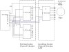
Do you have a circuit you could post.?
Using only LS138, IMO will not give the result you are expecting.
I am not confused,
Post a sketch.
sorry Eric, do you i will have to use external crystal?
what the meaning of IMO?
In my opinion... I would like to see a circuit diagram before looking at a program.
 , ok i will draw one then
 LIST p=16F628 ;tell assembler what chip we are using
include "P16F628.inc" ;include the defaults for the chip
ERRORLEVEL 0, -302 ;suppress bank selection messages
__config 0x3D18 ;sets the configuration settings (oscillator type etc.)
cblock 0x20 ;start of general purpose registers
count ;used in looping routines
count1 ;used in delay routine
counta ;used in delay routine
countb ;used in delay routine
tmp1 ;temporary storage
tmp2
templcd ;temp store for 4 bit mode
templcd2
Acc
endc
LCD_PORT Equ PORTA
LCD_TRIS Equ TRISA
LCD_RS Equ 0x04 ;LCD handshake lines
LCD_RW Equ 0x06
LCD_E Equ 0x07
org 0x0000
goto Start
Main_Text addwf PCL, f
retlw 'S'
retlw 'T'
retlw 'A'
retlw 'R'
retlw 'T'
retlw 'I'
retlw 'N'
retlw 'G'
retlw 0x00
Text_wire addwf PCL, f
retlw 'W'
retlw 'i'
retlw 'r'
retlw 'e'
retlw ' '
retlw 0x00
Text_pass addwf PCL, f
retlw 'P'
retlw 'A'
retlw 'S'
retlw 'S'
retlw 0x00
Text_fail addwf PCL, f
retlw 'F'
retlw 'A'
retlw 'I'
retlw 'L'
retlw 0x00
Start movlw 0x07
movwf CMCON ;turn comparators off (make it like a 16F84)
Initialise clrf count
clrf PORTA
clrf PORTB
clrf Acc
; clrf NumL
; clrf NumH
SetPorts bsf STATUS, RP0 ;select bank 1
movlw b'00010000' ;PORT A for LCD
movwf LCD_TRIS
movlw b'10000000' ;PORT B for Decoder
movwf TRISB
bcf STATUS, RP0 ;select bank 0
call LCD_Init ;setup LCD
Call Delay255
clrf count ;set counter register to zero
Main movf count, w ;put counter value in W
call Main_Text ;get a character from the text table
xorlw 0x00 ;is it a zero?
btfsc STATUS, Z
goto Sub_Main
call LCD_Char
incf count, f
goto Main
Sub_Main Call Delay255
btfss PORTA, 4
Goto Sub_Main
Call Delay255
movlw b'01000000'
movwf PORTB
Call Repeat
Call Delay255
movlw b'01001000'
movwf PORTB
Call Repeat
Call Delay255
movlw b'01010000'
movwf PORTB
Call Repeat
Call Delay255
movlw b'01011000'
movwf PORTB
Call Repeat
Call Delay255
movlw b'01100000'
movwf PORTB
Call Repeat
Call Delay255
movlw b'01101000'
movwf PORTB
Call Delay255
Call Repeat
movlw b'01110000'
movwf PORTB
Call Repeat
Call Delay255
movlw b'01111000'
movwf PORTB
Call Repeat
Call Delay255
movlw b'00000000'
movwf PORTB
Call Repeat
Call Delay255
movlw b'00001000'
movwf PORTB
Call Repeat
Call Delay255
movlw b'00010000'
movwf PORTB
Call Repeat
Call Delay255
movlw b'00011000'
movwf PORTB
Call Repeat
Call Delay255
movlw b'00100000'
movwf PORTB
Call Repeat
Call Delay255
movlw b'00101000'
movwf PORTB
Call Repeat
Call Delay255
movlw b'00110000'
movwf PORTB
Call Repeat
Call Delay255
movlw b'00111000'
movwf PORTB
Call Repeat
Call Delay255
Goto Start
Repeat Call Check
Call Delay255
bsf PORTB, 0
Call Check
Call Delay255
bcf PORTB, 0
bsf PORTB, 1
Call Check
Call Delay255
bsf PORTB, 0
Call Check
Call Delay255
bcf PORTB, 0
bcf PORTB, 1
bsf PORTB, 2
Call Check
Call Delay255
bsf PORTB, 0
Call Check
Call Delay255
bcf PORTB, 0
bsf PORTB, 1
Call Check
Call Delay255
bsf PORTB, 0
Call Check
Call Delay255
Return
Check Call LCD_Clr
Call Delay255
clrf count ;set counter register to zero
Check_Sub movf count, w ;put counter value in W
call Text_wire ;get a character from the text table
xorlw 0x00 ;is it a zero?
btfsc STATUS, Z
goto Check_main
call LCD_Char
incf count, f
goto Check_Sub
Check_main Call Delay255
movlw 5
Call LCD_Line1W
Incf Acc, w
btfsc Acc, 7
Goto Start
btfsc PORTB, 7
Goto Pass
Goto Fail
Ret Return
Pass Call Delay255
Call LCD_CharD
Call LCD_Line2
clrf count ;set counter register to zero
Pass_Sub movf count, w
Call Text_pass ;get a character from the text table
xorlw 0x00 ;is it a zero?
btfsc STATUS, Z
goto Ret
call LCD_Char
incf count, f
goto Pass_Sub
Fail Call Delay255
Call LCD_CharD
Call LCD_Line2
clrf count ;set counter register to zero
Fail_Sub movf count, w
Call Text_fail ;get a character from the text table
xorlw 0x00 ;is it a zero?
btfsc STATUS, Z
goto Ret
call LCD_Char
incf count, f
goto Fail_Sub
;Subroutines and text tables
;LCD routines
;Initialise LCD
LCD_Init call LCD_Busy ;wait for LCD to settle
movlw 0x20 ;Set 4 bit mode
call LCD_Cmd
movlw 0x28 ;Set display shift
call LCD_Cmd
movlw 0x06 ;Set display character mode
call LCD_Cmd
movlw 0x0c ;Set display on/off and cursor command
call LCD_Cmd ;Set cursor off
call LCD_Clr ;clear display
retlw 0x00
; command set routine
LCD_Cmd movwf templcd
swapf templcd, w ;send upper nibble
andlw 0x0f ;clear upper 4 bits of W
movwf LCD_PORT
bcf LCD_PORT, LCD_RS ;RS line to 0
call Pulse_e ;Pulse the E line high
movf templcd, w ;send lower nibble
andlw 0x0f ;clear upper 4 bits of W
movwf LCD_PORT
bcf LCD_PORT, LCD_RS ;RS line to 0
call Pulse_e ;Pulse the E line high
call LCD_Busy
retlw 0x00
LCD_CharD addlw 0x30 ;add 0x30 to convert to ASCII
LCD_Char movwf templcd
swapf templcd, w ;send upper nibble
andlw 0x0f ;clear upper 4 bits of W
movwf LCD_PORT
bsf LCD_PORT, LCD_RS ;RS line to 1
call Pulse_e ;Pulse the E line high
movf templcd, w ;send lower nibble
andlw 0x0f ;clear upper 4 bits of W
movwf LCD_PORT
bsf LCD_PORT, LCD_RS ;RS line to 1
call Pulse_e ;Pulse the E line high
call LCD_Busy
retlw 0x00
LCD_Line1 movlw 0x80 ;move to 1st row, first column
call LCD_Cmd
retlw 0x00
LCD_Line2 movlw 0xc0 ;move to 2nd row, first column
call LCD_Cmd
retlw 0x00
LCD_Line1W addlw 0x80 ;move to 1st row, column W
call LCD_Cmd
retlw 0x00
LCD_Line2W addlw 0xc0 ;move to 2nd row, column W
call LCD_Cmd
retlw 0x00
LCD_CurOn movlw 0x0d ;Set display on/off and cursor command
call LCD_Cmd
retlw 0x00
LCD_CurOff movlw 0x0c ;Set display on/off and cursor command
call LCD_Cmd
retlw 0x00
LCD_Clr movlw 0x01 ;Clear display
call LCD_Cmd
retlw 0x00
Delay255 movlw 0xff ;delay 255 mS
goto d0
Delay100 movlw d'100' ;delay 100mS
goto d0
Delay50 movlw d'50' ;delay 50mS
goto d0
Delay20 movlw d'20' ;delay 20mS
goto d0
Delay5 movlw 0x05 ;delay 5.000 ms (4 MHz clock)
d0 movwf count1
d1 movlw 0xC7 ;delay 1mS
movwf counta
movlw 0x01
movwf countb
Delay_0
decfsz counta, f
goto $+2
decfsz countb, f
goto Delay_0
decfsz count1 ,f
goto d1
retlw 0x00
Pulse_e bsf LCD_PORT, LCD_E
nop
bcf LCD_PORT, LCD_E
retlw 0x00
LCD_Busy
bsf STATUS, RP0 ;set bank 1
movlw 0x0f ;set Port for input
movwf LCD_TRIS
bcf STATUS, RP0 ;set bank 0
bcf LCD_PORT, LCD_RS ;set LCD for command mode
bsf LCD_PORT, LCD_RW ;setup to read busy flag
bsf LCD_PORT, LCD_E
swapf LCD_PORT, w ;read upper nibble (busy flag)
bcf LCD_PORT, LCD_E
movwf templcd2
bsf LCD_PORT, LCD_E ;dummy read of lower nibble
bcf LCD_PORT, LCD_E
btfsc templcd2, 7 ;check busy flag, high = busy
goto LCD_Busy ;if busy check again
bcf LCD_PORT, LCD_RW
bsf STATUS, RP0 ;set bank 1
movlw 0x00 ;set Port for output
movwf LCD_TRIS
bcf STATUS, RP0 ;set bank 0
return
;end of LCD routines
endwell, here is my circuit..

yes as said by eric the active low out cannot sink the current of other outputs
maybe u can use a 1:8 multiplexer (and connect the input to Vcc) or look for another part number with trisate outputs
yes the lcd display routines take up most of the program ..
to me it seems that it would not be necessary to display the pass/fail for each wire ..
maybe scan through all the 100 wires and then just say if all are ok .. or the list of wires which are not (remember to leave some delay for the user to read the result