Continue to Site

Welcome to our site!

Electro Tech is an online community (with over 170,000 members) who enjoy talking about and building electronic circuits, projects and gadgets. To participate you need to register. Registration is free. Click here to register now.

  • Welcome to our site! Electro Tech is an online community (with over 170,000 members) who enjoy talking about and building electronic circuits, projects and gadgets. To participate you need to register. Registration is free. Click here to register now.

Constant Current Source for PT100 circuit

Status
Not open for further replies.

sameerk

New Member
Hi,

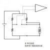
I am trying to develop a PT100 (RTD) based circuit. I have a PT100 connected in a Wheatstone bridge.
The bridge is excited with +5v supply and has
4k7-RTD and 4k7-100e resistance arms. (1% resistors)
I wish to apply a constant current source to this bridge and pass a near 1mA current through each bridge arm.

Not sure with the change in resistance of RTD(PT100) how the current can still remain constant at @ 1mA! .... Please throw some light.

Can I implement the current source using LM134/234/334?

Please share your ideas/experience about the exact circuit that I can try out.
 
Yes, an external (to the bridge) constant current source will do it. Google "constant current source circuit". Lots of possibilities, including a simple LM317.
 
Yes, an external (to the bridge) constant current source will do it. Google "constant current source circuit". Lots of possibilities, including a simple LM317.
The LM317 has a minimum load current of 10mA so would not work for a 2ma constant current source.
 
The LM317 has a minimum load current of 10mA so would not work for a 2ma constant current source.

So shunt the other 8mA to ground through a parallel resistor. If I was doing this, I would use the LM317 that I have on hand rather than drive across town to buy something more elegant, or wait several days (and pay shipping) to get something via mail order.:D
 
So shunt the other 8mA to ground through a parallel resistor. If I was doing this, I would use the LM317 that I have on hand rather than drive across town to buy something more elegant, or wait several days (and pay shipping) to get something via mail order.:D
The current through the bridge won't be constant if the resistance of the bridge changes and it has a fixed resistor in parallel with it. The current change might be insignificant, but the effective output impedance of the "current source" driving the bridge will be ≈1.2k instead of infinity.
 
Last edited:
Actually, 600Ω.

I'm not sure that it matters a hill of beans, anyway. Here are three identical bridges excited with 2mA, 10ma shunted by 600Ω, and 4.8V. The RTD resistance is varied from 75 to 125Ω.

The top plot pane shows the differential output of circuit C (the other two are the same on this scale).

The middle plot pane shows the difference between the output of C and B, and the difference between C and V. Note that the largest difference is a measly 66uV (out of 25mV) of this range.

Finally, the last pane shows the actual current through the RTD in the three versions of the circuit.

Driving a four-arm bridge with a constant-current source vs a voltage source has benefit when the tempco of the four arms is matched. By definition, in this circuit, the four arms do not have the same tempco, so why bother driving it with a constant current source, anyway?
 

Attachments

  • Draft30.png
    Draft30.png
    44.4 KB · Views: 3,716
Last edited:
Guys

Thank you so much for such quick responses.
Mike, thank you for your well directed efforts.

So, does that mean I should use a CV source instead?
What may be a better (component) choice for that?
 
You do not need a constant current source with a 2 or 3 lead RTD wheatstone circuit. In fact, with a balanced bridge you don't even have to have a stable voltage supply. Equal currents will be provided by the precision of your resistors and balancing of the RTD with the variable pot. The only concern might be temperature stability on the circuit board. the change in potential created by the RTD (and consequently change in current in that leg) is what causes current to flow through the ammeter and deflect the needle. It seems like regulating the current might be counter productive in the balanced design.

Are you building a balanced bridge with an ammeter or an unbalanced with a voltmeter? The unbalanced voltmeter circuit is a little more complicated, but I still see no justification in regulating the current for typical applications.

Constant current is typically used for 4-wire RTD applications, which isn't being accounted for in the responses here. Is your RTD a 2,3, or 4 wire sensor? 4 wire circuits are for nullifying lead resistance, but is typically not neaded unless your talking about a long distance. Are you making a long cable run between circuit and sensor?

Why not go with a simpler 2 or 3 wire design?
 
Hi

Mine is a 3-wire RTD wheatstone bridge.
I shall amplify the ΔV of the bridge.
I am not sure whether to answer this as a 'balanced bridge with an ammeter or an unbalanced with a voltmeter'.

My intention is to have the stable arm of the bridge (4k7-100e) produce a fixed Voltage and only the ΔR of the RTD should produce a proportional ΔV in the design.

ΔV to an amplifier would essentially be an unbalanced voltmeter type bridge.
And three wire? Explain why constant current is needed in your design? Can you post your schematic? Constant current is typically used when lead resistance is an issue. 4 wire designs overcome that problem. But your using 3 wire, so please explain the need for constant current?
 
Your circuit resembles this, right?

Do you see that the bridge itself is your source of regulation?

In fact, a constant current source eliminates the need for a bridge altogether, because the voltage drop across the RTD in series with a single resistor would suffice as long as no current variability occurs.
 

Attachments

  • 3 wire bridge.JPG
    3 wire bridge.JPG
    25.9 KB · Views: 3,529
Hi ke5frf

Thank you for your interest.
I understand that constant current is not needed in my bridge design.

However, do you think I need a constant voltage source OR just a stable voltage output of a +5v SMPS would be fine?

The schematic you posted is mostly similar to my circuit.
I am saying mostly as I have connected the 3-wire RTD up side down and one of the two wires goes to ground and other goes to the other arm's 100e resistor

to ^ 4k7 GND 100e (bottom - other arm)
^ ^ ^ (CONNECTION Details)
I_lRTDl__I_____I

Hope I am clear!
 
Last edited:
I think a regulated SMPS output would typically suffice for a hobbyist circuit, but I wouldn't trust a wal-wart (for example) to regulate a critical temperature controller on the Space Shuttle :)

It depends on the purpose of your final product. Are you building a digital thermometer for a scientific test apparatus, or are you going to be monitoring the soil temperature in your flower garden?
 
Yes, an external (to the bridge) constant current source will do it. Google "constant current source circuit". Lots of possibilities, including a simple LM317.

Using an LM317L he can achieve a constant current of 1mA without problem.

Boncuk
 
Hi ke5frf

Thank you for your interest.
I understand that constant current is not needed in my bridge design.

However, do you think I need a constant voltage source OR just a stable voltage output of a +5v SMPS would be fine?

The schematic you posted is mostly similar to my circuit.
I am saying mostly as I have connected the 3-wire RTD up side down and one of the two wires goes to ground and other goes to the other arm's 100e resistor

to ^ 4k7 GND 100e (bottom - other arm)
^ ^ ^ (CONNECTION Details)
I_lRTDl__I_____I

Hope I am clear!
It's certainly not clear to me! If you don't have a schematic capture program, use something like Microsoft Paint.
 
However, do you think I need a constant voltage source OR just a stable voltage output of a +5v SMPS would be fine?

A few concerns that are to be considered:

1) Are you powering other circuits with your power supply? If other loads will be competing, especially any inductive loads, I think it would be adviseable to isolate your bridge circuit with a dedicated regulator. The added benefit would also be that noise coupled to your sensor leads would be isolated from your digital circuits to some degree.

2) Bridge resistor specifications: I think the most critical consideration is the TCR of your bridge resistors and their precision. The more stable and precise the better obviously. In thin film packages 5 PPM/°C TCR and .02% tolerance is available.

3) Further precision will be afforded by ensuring a regulated temperature for the bridge resistors vs the environment the RTD is exposed to. Obviously a portable device is more difficult to regulate, but fixed designs can incorporate a cooling fan with vented enclosure in a air conditioned environment. Take measures to heat sink components in circuits that might have variable heat conditions.

How accurate your application has to be will determine the lengths you go to designing all of this.
 
It's certainly not clear to me! If you don't have a schematic capture program, use something like Microsoft Paint.

I agree, a better illustration would certainly be fitting. I don't think it makes much difference though in terms of his questions.
 
hi Ke5frf

I am doing this circuit for some kind of industrial control application.
I am trying to use AD623 INAmp after this bridge but as of now not consolidated on that design.
Uploading the schematic for ease of understanding. btw, I am not very good at drawing things on computer!
 
btw, at present I am planning to power the whole circuit with the same SMPS.
do you think i should go for another regulator just for the bridge in case i need a 0.5 deg C resolution from my application and the range I am targetting is -20 to 200 deg C?
 

Attachments

  • PT100_1.JPG
    PT100_1.JPG
    8.5 KB · Views: 1,220
As far as sensor lead noise is considered, is it a fair idea to have disc capacitors put up around both the lower resistances of the bridge?
I am at present using 1% resistors. Not sure if I may get the TCR type you mentioned. I shall check though.
 
Status
Not open for further replies.

Latest threads

New Articles From Microcontroller Tips

Back
Top