Continue to Site

Welcome to our site!

Electro Tech is an online community (with over 170,000 members) who enjoy talking about and building electronic circuits, projects and gadgets. To participate you need to register. Registration is free. Click here to register now.

  • Welcome to our site! Electro Tech is an online community (with over 170,000 members) who enjoy talking about and building electronic circuits, projects and gadgets. To participate you need to register. Registration is free. Click here to register now.

Composite video

Status
Not open for further replies.

Dr_Doggy

Well-Known Member
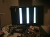
unfortuneately due to the HD failure, my responses for this post were lost, so here i am, and with my new 1881 vsync chip and uC,
i was able to get that line much straighter using the help from this guy:
http://www.garydion.com/projects/videoverlay/

i was also able to narrow that line to a dot, when i found the "page sync" on the 1881 aswell


however i read the wiki and do not understand what they are saying about harmonic frequencies to get color, are they saying that frame 1 is red, frame2 is green and frame3 is blue?

i am also having a problem on the pic side, where i am using:

latb1=1; black on screen
....
latb1=1; black on screen
latb1=0; white on screen //to get my white line
latb1=1;black on screen

however each single instruction is taking 100ns on the scope, i even got a 13mhz external clock, and changed OSC to HSPLL, since that was the only one to work, but is this right, and maybe i am missing other instructions?>if that single instruction takes so long i wont have time to bit bang any data, how do i get this clock speed faster, this is my first external clock, now using the 18F1230... how should i approach this??
right now i am thinking counters, shift registers, and fast external parallel eeproms??
 

Attachments

  • 1355118124424.jpg
    1355118124424.jpg
    232.5 KB · Views: 203
  • 1355291287575.jpg
    1355291287575.jpg
    217.7 KB · Views: 194
Last edited:
no, color is controlled by phase angle, not by frame. that's why there is a color burst sync pulse on the backporch of the line sync.
 
however i read the wiki and do not understand what they are saying about harmonic frequencies to get color, are they saying that frame 1 is red, frame2 is green and frame3 is blue?

As I mentioned previously, read up how PAL/NTSC work - the above sentence is complete meaningless rubbish.

If you want to generate a colour signal, use an encoder chip (as old computers used to use), and generate RGB+sync in the PIC.
 
to generate color, you need a 3.58Mhz subcarrier (for NTSC). the particular color shown is related to the phase of the subcarrier during the line referenced to the chroma burst. the burst phase locks a reference oscillator, which is used to compare against the chroma subcarrier. if the subcarrier is in phase with the burst, the color is yellow. as the phase shifts, the color changes according to the following:
60 degrees=red
120 degrees=magenta
180 degrees=blue
240 degrees=cyan
270 degrees=green

if you look at a picture on a studio reference monitor in underscan mode, you will see a thin yellow line down the left side of the screen. this is the chroma burst.

composite video is an analog combination of monochrome video, chroma, horizontal sync and vertical sync. the digital logic is only half the battle. your PIC can probably handle the functions that control the analog circuits that generate the signal, and the real "magic" takes place in the analog part of the system. there are chips that handle most of the analog parts of the system, such as https://www.electro-tech-online.com/custompdfs/2012/12/AD725.pdf

there are some support circuits that need to be built for the AD725, such as the chroma reference oscillator (a good, stable 3.58Mhz crystal oscillator), and some simple DAC circuits to generate at least 3 or 4 analog levels for each color (early "TV typewriter" designs used a simple resistor ladder fed by logic level outputs)
 
Why do you need a 1881 vsync chip? It's easy enough to decode the vsync and hsync pulses with the microcontroller, plenty of people have done video text overlay with just a microcontroller.

To display data generally you setup the data in the blanking (non visible) period, then display it in the visible scan period.
 
thnx, that clears up that a bit, i think ima get one of those enceoders and see what it does on the scope.

but back to my other prob an in relation to your ? RB , i got the decoder since it was the simplest schematic and i had no idea how sync worked when i got in to this,

but i am now running to speed problems again where im running the pic@13mhz on xt clock but a single bit instruction works out to 100ns and gives me a resolution of 250x800, but even by putting the bits in a "for" loop brings the horizontal down to 50 pixles, but how i do i go faster? boosting the clk higher may help a bit, is there a code strategy i should use, or maybe i should ask for a walkthrough to setting up my external clock?? the atTINY can't be that much faster, and the demo he was using more complex logic with 232, and able to get good res with characters, so i must be doing something wrong...

(i may be inverted, but problem remains)

plan b is to run a parallel eeprom on some counters triggered with 1881 and clock, and just program the data with pic
 
You want more speed! You say your instruction time is 100nS. This is 10mips. So the clock is 40mhz. Most of the larger PICs have a 4x PLL so a 10mhz crystal will make a 40mhz internal clock. The 18F1230 is only good for 40mhz. It might work with a 13mhz xtal but it is designed for a 10mhz xtal.

To get more speed you need to do better software. Loops are slow. The difference between 10 and 13mhz is small.
A loop could take 1uS (10 instructions) or maybe 20 instructions. In a loop you need to test if done every time. This takes time. If you need to do something (fast) 10 times just do it 10 times (no loop). This takes more PROM but the speed is higher.

There are some PICs that have DMA. There are some application notes from PIC. These parts are hard to find because MicroChip does not have a list of DMA parts. PIC DMA will move data to/from memory to SPI or Port very fast with out CPU effort.
 
k, i will give it a second try, looping was taking that long, i think i will stick with the eeprom and counters thou, , since i notice that my pic dont have that much memory anyway, originally i used a switch command to differ from the vertical lines, then 200xsetport1's, however i ran of of space after 2 lines that way too. plus the extra bits on the eeprom allow me to program several overlays, i will be using1bit B/W graphics....but i now need to wait for my new parallel eeprom, lol since I realised the first one i got is OTP, no good for rookies!

since i have drifted to the topic though, i remember in cow(GCGB) you could set things like rs232 to hardware program or software program, also when i write a rs232 i use my own subroutines on the first PORT pin i wire in to, as this is an example of software programming,

Ialso know that when you guys would do it you would probabally connect rs232 to the proper TX/RX pins from datasheet, and use registers in the PIC, is this an example of DMA or is that just hardware control registers, separate from a DMA and still taking its time?
 
Last edited:
It's not a trivial project generating real time video from a little PIC! It is quite hard and you need the skill to be able to write very efficient code that is also synchronised within the limits of the video frame and line timings.

When I did the 10 megapixel VGA test with a PIC 18F running at 40MHz I used the SPI module to automatically clock out the pixel data. That is a common method that many people have used. The SPI module will run at 10 MHz and you only need to load 1 byte into the SPI module every 8 PIC instructions;
https://www.romanblack.com/easypic6_proj1.htm (about half way down the page)

**broken link removed**
 
It's not a trivial project generating real time video from a little PIC!
no doubt there,

However MR RB id be very interested in how you setup your code, especially that processing part that takes all the sync time, the for loop is my fav, but way too slow, i also wonder did you build a character map?

I am happy that I am meeting the timing requirements so far, but

I am sad though as the ad725 is smt, and i cannot solder with that, I also wonder how you guys are making those nicely pro pcbs, is there any chance i have access to that technology>?
i have simulators to draw the boards, but nowhere to go from there.

and about that color burst sync pulse pin? what does it do??...ie would i be able to use it to output some color? even if i could turn the whole overlay from white to red would be cool enough.

OHYA, and a last thing, i am still getting very small horizontal jitters, how should i correct this?
 
Last edited:
I am sad though as the ad725 is smt, and i cannot solder with that, I also wonder how you guys are making those nicely pro pcbs, is there any chance i have access to that technology>?
i have simulators to draw the boards, but nowhere to go from there.

Soldering SMT takes some skill, but can be done with practice. SOICs are easy, but QFPs are .5mm and very hard. The girls on our soldering line could do it with one swipe per row. It looked so easy (THEY made it look so easy) I tried it myself once, and got one long blobular line of solder. However, I have soldered many ATMEGAs 44 pin QFPs (.5mm)... the trick is to solder the row, blobular mass and all, then go back and clean up shorts with solder wick. I've sent many boards to the field (none to return to date, knock on wood) using this technique.

As for the professional PCB layouts, we are, afterall, professionals. There are loads of free software out there to layout PCBs with. I use the PADS PowerPCB suite, which cost mega$$$, and would offer to do one for you, but this is my bread and butter so have to decline to do so. If it's a simple single layer board, kits can be bought that you can etch your own circuit board.
 
Last edited:
ya, thats what i thought, just wishing, i already have the software, but hoped that there was a place/company that would do individual custom pcb's,. just i noticed nigels board was pro done, and was hoping that he had not purchased it or used internal corporate resources, i think thou i will just stick to my perf boards and phone wire nodes then, i find etching to be a waste of time since usually my schematics are small and only take a few hours anyway.
 
... However MR RB id be very interested in how you setup your code, especially that processing part that takes all the sync time, the for loop is my fav, but way too slow, i also wonder did you build a character map?
...

I think from the "sync" time you mean the actual display pixels time? I did that in an assembler sequence that just loads a byte from RAM into the SPI module, every 8 instructions exactly.

My project was VGA not composite, but the principle is the same, the SPI module will output 8 pixels at a rate of 10 pixels per uS (assuming a PIC18 running at typical 40MHz).

...
and about that color burst sync pulse pin? what does it do??...ie would i be able to use it to output some color? even if i could turn the whole overlay from white to red would be cool enough.

At this point I would suggest you forget colour on composite video, due to the complexity and that you are just starting. Making a white on black video result work well would be a good first project and will provide enough challenges I think. ;)

See above Nigel posted a link to a project he did with colour composite video, you can see there's a lot of hardware complexity there compared to the simplicity of white on black.

...OHYA, and a last thing, i am still getting very small horizontal jitters, how should i correct this?

These are the "little things" that really need to be sorted and are not that easy and will take a lot of your coding time. When generating video you need to generate the horiz sync pulse at an EXACT timing (right down to one PIC instruction every time), you also need to get the horizontal line period the right period, and the same period every time.

If doing video overlay on an existing video signal it's the same issue but in reverse! Your PIC needs to sense the hsync pulse and syncronise itself exactly to that pulse. You can't just use a loop to sense when the pulse start as the PIC will be 0-2 instructions in sync error, randomly. Most people use an "interrupt on pin change" feature to get exact sync timing from the incoming hsync pulse.
 
Edit I wrote this before reading romans comments about the spi port.

I have done this and I found a way to increase the speed, I got it to work fairly well with a 16f628 of all devices, only my design was only black and white, and seeing as I'm in the UK its also pal not ntsc.

I dont know if you can do this with colour, but to get the speed I used an entire o/p port, the 8 pixels to be displayed are loaded into the port and then shifted out through bit 0, shifting only takes 1 instruction, the only thing is loading the port takes 2 or 3 so you will have gaps on screen, this is ok for text though.

You might be able to use a pic with an spi port too and save the i/o.

Using video chips is a good idea, esp for colour, but it has been done with just a pic.

Also I found some telly's are sensitive to the vertical sync pulse train, I wanted to use my project on some vinatge sets, which got really upset with the signal, unless the vsync is correct on old tellys you get a dc offset which messes up the video amp, not a problem if your tv isnt a relic.

::respect to you roman, that video gen using 3 resistors looks like a nice piece of work even if the code isnt neat.
 
Last edited:
Using video chips is a good idea, esp for colour, but it has been done with just a pic.

Are you sure?, I seriously doubt it :D

Romans VGA example is impressive, but there's no 'colour' just three monochrome images for the VGA - just as with the examples I posted, except they were PAL, but used hardware to create the colour from the three monochrome images.
 
RB:
A)got it, assembly:(, and you loaded the RAM, after each sync trigger, before the "line hits the screen"?
B) aware, and i bumped up the clock to the 40 mhz, before was getting that 240horizontal resolution in 2bit color using LAT instructions on the 13mhz clk, IDK assembly bt have planB neway, should workout,
C) already have! just investigating! 2bit color Challenges overcome!
D) noted, also noticed he used ad724 aswell, oops was this one:https://www.qsl.net/zl1wtt/images/Bar_PCB.jpg , but how did he get pcb?
E/F:BUSTED ME! will use the interrupt

contd;

ya, i dont think pic will do it alone, if i understand phase angle that is the slope that things take to rise and fall, so ultimately need higher frequency, on100ns port switching, no way i can. espically if my numbers are correct, 10mhz=100ns/instruction. i presume then 40mhz=still not fast enough.

thnx again guys, it has been a learning curve, just waiting on parts, bench is packed up now till i move this year, in the mean time ima go brush up on my java, overall i think what ima do is:

goto 40mhz on pic;
stick with 2bit color;
create graphics array instead of text;
use 50ns parallel XTeeprom to feed 80mhz shift register, as dr pepper suggested, and drive eeprom with 2x10bit counters, all <20$
and use pic for Bluetooth relay to program XTeeprom from a nice UNCOMPRESSED! jpeg file (found amazing 2bit conversion software)
....... and maybe other basic drive functions

sound good?
 
Not sure what you meantt when you said are you sure Nige.

Colour games have been done with pic16f's, might use a similar technique to romans but still colour.

Using video gen chips is what nearly every homw computer does, if you have processing power its better off doing the crunching rather than generating video, unless its a chip that just does one job displaying images or text.

The problem with lesser pics is memory, my project can only display half of the screen as there isnt sufficient space to hold all the data.
 
Status
Not open for further replies.

Latest threads

New Articles From Microcontroller Tips

Back
Top