Continue to Site

Welcome to our site!

Electro Tech is an online community (with over 170,000 members) who enjoy talking about and building electronic circuits, projects and gadgets. To participate you need to register. Registration is free. Click here to register now.

  • Welcome to our site! Electro Tech is an online community (with over 170,000 members) who enjoy talking about and building electronic circuits, projects and gadgets. To participate you need to register. Registration is free. Click here to register now.

Component identification in a touch operated light switch

Status
Not open for further replies.
Getting further into the data sheet I see that although it says max vdd is 0.3 to 7.5v it does say except for MCLR which is 13.25v and except RA4 which can go to 8.5 for some reason. so apparently it is safe to take MCLR higher than VDD but that's on the MCV18E and we are still not certain the chip I have is that one, and if I damage one of mine it writes off a £29 switch if I can't buy the chips and extract the software to program them, I'm thinking it would be foolish to try?

Fairly obviously a higher voltage is perfectly OK on MCLR, because that's how you get in programming mode :D It's a special function of that individual pin. As I mentioned in post #10, RA4 is an open-drain pin - this allows it to go slightly higher than the other pins - but basically just till the protection diode catches the higher voltage, so the small extra voltage capability is not really much use.

I'm somewhat bemused how the MCV18E popped up in this thread - it's just one of MANY 18 pin PIC devices (and an extremely obscure one), and if the device in question is a PIC it could be anyone of them - there's nothing specific to point towards the MCV18E. It must be the most obscure PIC series numbering there ever was - not listed at MicroChip, not listed at MicroChip Direct, not listed at Distributors, even Google finds sod all about it. As I suggested above, I can only imagine it's an alternative label for a more normal PIC. THere's nothing 'special' in the MCV81E datasheet, it's just a low spec 16F device.

I agree that it would be foolish to try, particularly as it's VERY likely read protected if it is a PIC anyway.

I was just watching a youtube video where a chap is describing the components on a circuit board and he says and they have a microcontroller. what I notice is the screen print designation is U1 which happens to be the same designation as the unknown chip on my board, so is "U" a universal designation for micro controllers in pcb layout?

Could be U, could be IC, could be anything you want - just checked on one of my boards and it's IC2. It basically depends on whoever created the component, and if the board designer just used the default reference.

It's quite common to have multiple PIC's on the same board - their low cost means it makes products cheaper and smaller, by replacing multiple IC's with just one.
 
I just added an edit to the last post, now we are on page two I thought I better mention it in case you don't go back to page one and see it,
 
Quick question, does the programmer apply 13 volts to the chip when reading?
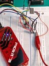
I have this chip connected to the Pickit 3 using 12 clk 13 dta 4 mclr and of course 4 and 14 for power

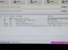
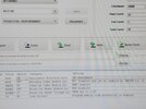
if I try to use the Pickit to supply power it bitches about connections, if I connect external 5v it no longer complains and appears to work, but when I read I get no voltage on the MCLR which is why I ask, I have tried all of the listed MCV types from the 18E up it's complaining about the 18E but seems happy with the 18 A, but every single read of all types says code protect is on, but I am not certain it is actually reading the chip, a blank check on all say the chip is not blank, but is it reading it.
I took some pictures, the warning box was on the MCV18E+
 

Attachments

  • IMG_20221129_145426_MP.jpg
    IMG_20221129_145426_MP.jpg
    1.7 MB · Views: 153
  • IMG_20221129_151518_MP.jpg
    IMG_20221129_151518_MP.jpg
    4.9 MB · Views: 157
  • IMG_20221129_151136_MP.jpg
    IMG_20221129_151136_MP.jpg
    8.6 MB · Views: 147
  • IMG_20221129_151223_MP.jpg
    IMG_20221129_151223_MP.jpg
    3.8 MB · Views: 162
  • IMG_20221129_151613_MP.jpg
    IMG_20221129_151613_MP.jpg
    4.2 MB · Views: 147
  • IMG_20221129_151805_MP.jpg
    IMG_20221129_151805_MP.jpg
    9.2 MB · Views: 152
The PIC needs to be powered (so 5V or whatever), the 13V is only applied to MCLR - however, you can set the PICKit to provide power to the chip, it's on one of the setting options.

I'm still bemused why you're checking MCV devices?, as there's nothing to suggest it's one of those - and there are far more PIC 18 pin 16Fxxxx devices.

From what I can tell from the MCV18E datasheet it doesn't have device ID?, so the PICKit shouldn't be able to read what the chip is - as it can with later devices (the MCV18E datasheet is from 2009).

If it's code protected that doesn't mean it will read as blank - blank means all bits are '1', programming simply changes '1' to '0' where required. I don't know as I've ever tried to read a protected PIC?, I never protect them, and if I did once try it?, it's wasn't this century and I can't remember how it might have read (or if I even did it).

As far as I'm aware, if it's an old device without device ID, then you should be be able to attempt to read it with it set to any compatible non-device ID PIC - but if you select a device ID type, it will just give an error message that it can't find the correct ID.

You might try selecting the 16F628, another random (but much more common) 18 pin PIC, that pre-dates device ID. PIC's use various programming algorithms, but most are pretty similar for similar'ish' devices.
 
I don't know as I've ever tried to read a protected PIC?
If I remember correctly, the readback is masked so only the low bits (or high bits?) of each program location are returned with their programmed values, with all 1s or all 0s for the remainder.
 
The reason I am working with the MCV devices is because member rjenkinsgb pointed out that they have the clk and data on pins 12 and 13 which is what this chip of mine has, the pic chips don't use 12 & 13 for clk and data do they?
Having said that I did try the 16F628 and the Pikit3 complained things were wrong, I think it was ID I will check again tomorrow

I did say in my post that I tried the internal power and it complained so I had to use external power?
the question was, does it apply the 13 volts to mclr to read or just to write!! I know it's on mclr

I think that because the pikit 3 and the Microchip software expects to get a chip ID from a 16F628 or similar and this chip does not give it, it complains and will not allow further action
 
Last edited:
The reason I am working with the MCV devices is because member rjenkinsgb pointed out that they have the clk and data on pins 12 and 13 which is what this chip of mine has, the pic chips don't use 12 & 13 for clk and data?

Yes they do, as I pointed out here long ago (post #6) - the MCV devices ARE just PIC chips.

Having said that I did try the 16F628 and the Pikit3 complained things were wrong

I did say in my post that I tried the internal power and it complained so I had to use external power?
the question was, does it apply the 13 volts to mclr to read or just to write!! I know it's on mclr

I think that because the pikit 3 and the Microchip software expects to get a chip ID from a 16F628 or similar and this chip does not give it, it complains and will not allow further action

There's no chip ID in a 16F628, and things only complain if it expects to read an ID - if you select a chip that has one.
 
Oh ok, you like to quote posts but I won't quote the one where I said I don't know much about Microcontrollers :D
 
Last edited:
Why doesn't this forum allow smiles in the middle of a text? I had to post separate to say that I had just been looking at the data sheets and trying to grasp it and couldn't without the smile above being at the end of everything? Anyway I see that some of the PIC say RB6 and RB7 without mentioning they are the programming pins clk and data Mclr always seems to be pin 4 but if you remember I pointed out that on my chip that is an output going to a 4k7 on a transistor base?
The first time I tried to read the chip using 16F628 and with Mclr on pin 4 the pikit complained too much current was being drawn, check the wiring?

So how do you know if the chip has one? ID that is
 
Just tried the 16F628 again and this is what I get, I have slowly increased the voltage but no good, can't connect the external PSU at the moment as I took it to the lounge PC
Bummer! can't find the file it looks like the screen capture didn't save
 
Last edited:
Just in case here is the chip that is on the touch pcb, I can't find that anywhere either, I'm not having much luck with this.
Anyone have any idea's please ?
 

Attachments

  • 2020_1220_034724_001.JPG
    10.2 MB · Views: 153
Last edited:
Why doesn't this forum allow smiles in the middle of a text? I had to post separate to say that I had just been looking at the data sheets and trying to grasp it and couldn't without the smile above being at the end of everything? Anyway I see that some of the PIC say RB6 and RB7 without mentioning they are the programming pins clk and data Mclr always seems to be pin 4 but if you remember I pointed out that on my chip that is an output going to a 4k7 on a transistor base?
The first time I tried to read the chip using 16F628 and with Mclr on pin 4 the pikit complained too much current was being drawn, check the wiring?

PICKit3's can only supply very little current, and they seem easily damaged which further decreases their current capability, the PICKit4 has much greater capacity - but the PK3 should be fine on just a bare chip.

So how do you know if the chip has one? ID that is

From it's datasheet - here's the section from the (28 pin) PIC I'm currently using, the 16F18857. There's no such section in the MVC81E datasheet, and the 16F628 is FAR older.

I'm not sure when device ID first appeared?, it was a feature I would have liked back when I was writing PicProg and WinPicProg (the worlds first Windows PIC programmer software) - but there were no such features back then.

Basically, modern PIC's have it - old ones don't :D

Device_ID.png
 
Morning Nigel, You wrote that! well done, I remember using picprog years ago to prog a 1684 and p16pro.
Any idea about the touch chip above? this is the chip I mentioned before that's on the touch pcb and has input from the pad you touch and sends it's output to the pic we can't identify, what is it with all these obscure components? I was also working on a Victron shunt yesterday, from a solar power system, it has two chips I can't find on the net, both obviously regulators, you would think they would be easy! Luckily I am 70 now and don't have to do it every day anymore.
 
Last edited:
Morning Nigel, Tou wrote that! well done, I remember using picprog years ago to prog a 1684 and p16pro.
Any idea about the touch chip above? this is the chip I mentioned before that's on the touch pcb and has input from the pad you touch and sends it's output to the pic we can't identify, what is it with all these obscure components? I was also working on a Victron shunt yesterday, from a solar power system, it has two chips I can't find on the net, both obviously regulators, you would think they would be easy! Luckily I am 70 now and don't have to do it every day anymore.

A lot of manufacturers use 'in-house' numbers, this is partially to prevent people knowing what they are, but also so they can source devices from multiple suppliers. This is more common with transistors than specialist IC's (where there's often only one manufacturer) - so you contact semiconductor manufacturers and order devices of a particular specification, and give them the number you want printing on it (in house number). You then have multiple sources, yet can keep all the parts under one part number, stored together.

The other thing of course is that most of these products come from China, with Chinese manufactured components, often with little or no information about them, and obscure manufacturers you've never heard of. If you do ever manage to find a datasheet, it's usually in Chinese. SM components are particularly troublesome, as small ones often just have a code on them, rather than an actual number - and it's pot luck if you can find what the code means, and even if it only refers to a single device.
 
Well, I don't know if anyone is still interested but I spent the day trying to read this chip, I tried with Pickit 3 and Pickit 2 with the MCLR on pin 4 they say there is a problem with VPP check your wiring, Having spent a lot of yesterday on it too, I decided to systematically move the MCLR connection to different pins I tried 6,9 10 11 17 18 But got the same result on all. on both programmers I tested that the programmers were ok with PIC16F648A and 16F627A and 16F1847 ( Which were the only PIC chips I had ) Depending on which programmer was connected I would get device not supported on some but then they would work on the other, so the programmers are ok
As I said in a previous post why would they make a in circuit programming pad with clk and dta and gnd and 3volts but no MCLR, is it possible this is some kind of Micro that does it all without it? I have certainly proved it's not happy to have VPP on pin four and the others I tried, I didn't try all of them as some were obviously in use for other things and it would be impossible to in circuit program without cutting tracks to disconnect them, but I presume as it was designed for in circuit programming you wouldn't have to do that. I am baffled now.
Out of interest I soldered the test chip back onto a switch and it functions perfectly as just a touch switch, it just will not operate another remote switch
 
Last edited:
Hi Nigel I am still working on and off with this unidentified chip, as you know I am confused by the fact the ISCP only has Power, ground, clk and dta, no Mclr,
I found this in the data of the 16F54, sounds to me like all you have to do is hold 13 volts on pin 4 while you turn on and then it stays in programming mode. Have I misunderstood?

"Note 1: In the PIC16F54, the programming high voltage is internally generated. To activate the
Program/Verify
mode, high voltage of IIHH current capability (see Table 5-1) needs to be applied to MCLR input."

2.4 Program/Verify Mode
The Program/Verify mode is entered by holding pins
ICSPCLK and ICSPDAT low while raising VDD pin from
VIL to VDD . Then raise VPP from VIL to VIHH. Once in
this mode, the user program memory and configuration
memory can be accessed and programmed in serial
fashion. Clock and data are Schmitt Trigger input in this
mode.
The sequence that enters the device into the
Programming/Verify mode places all other logic into the
Reset state (the MCLR pin was initially at VIL). This
means that all I/O are in the Reset state (high-impedance
inputs

And if this is how it's done, are there other 18 pin Pic chips that have this feature? hopefully ones with no id
 
Possibly, but it still needs MCLR to access programming mode - as far as only two programming pins goes, it could be done using a boot loader, rather than an external programmer - but this requires the chip to have been programmed with a bootloader in the first place. This is how Arduino's work, with a pre-programmed boot loader rather than using a programmer.
 
Possibly, but it still needs MCLR to access programming mode - as far as only two programming pins goes, it could be done using a boot loader, rather than an external programmer - but this requires the chip to have been programmed with a bootloader in the first place. This is how Arduino's work, with a pre-programmed boot loader rather than using a programmer.
I thought about that, as I have actually done some Arduino programming, but I don't know of an 18 pin Micro-controller like the Arduino? I did find one 18 pin one called the Geni 18, power pins the same, but clk and dta on the wrong pins, I wonder if this chip is some Chinese obscure little controller like a mini Arduino, the Seeduino is to small, there are just too many types to troll through, Just for a giggle I emailed the customer service and asked them if they would be so kind as to inform me which Microcontroller is used in the switch, Nothing yet :) Can bootloaders be used with some pic chips then Nigel? I guess if they program them at the factory from the edge connector then surely the bootloader will still be in it?

Edit: I have just been reading about LVP, what if this chip is newer than we thought and it has LVP? It says here that chips with the LVP capability are sent from the factory in LVP mode with the LVP bit set, surely it would make sense for a manufacturer to leave it otherwise they have to use High voltage programming to change the bit on every chip they use, and if this chip is in LVP mode it would explain the lack of MCLR at the programming socket, it says the chip enters programming mode by an instruction down the data line, but the chip has to be at 5 volts VDD, well when the switch is in use the chip is at 3V vdd so presumably the ov and V+ on the programming socket get 5 volts when programming with the switch disconnected from any other supply?
I remember you saying if the chip was newer it would have an ID, well maybe it has, but we need to be in the LVP mode to see it? I have never done any LVP is it just a case of setting the Pickit 3 to that mode somehow Nigel?
Bob
 
Last edited:
Status
Not open for further replies.

Latest threads

New Articles From Microcontroller Tips

Back
Top