Continue to Site

Welcome to our site!

Electro Tech is an online community (with over 170,000 members) who enjoy talking about and building electronic circuits, projects and gadgets. To participate you need to register. Registration is free. Click here to register now.

  • Welcome to our site! Electro Tech is an online community (with over 170,000 members) who enjoy talking about and building electronic circuits, projects and gadgets. To participate you need to register. Registration is free. Click here to register now.

Component identification in a touch operated light switch

Status
Not open for further replies.

Dr Bob

Member
Hi Guys, I have a four touch operated Single pole change over light switches that can control a light from two locations.
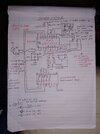
one pair is faulty, I spent hours drawing the circuit out and proved it's the main 18 pin chip that it faulty, to prove it I de soldered one from one of the spare switches and now it works, trouble is I cannot identify the chip to buy a replacement.
The chip is smd and has 18 pins, there are no crystals or ceramics so I don't think it's a pic chip and there are no wave forms on the pins with the scope, just DC voltages, so I think it's linear, it
has FMD at the top and under it B2C50DE or it might be ode but either way I find nothing on the net, anyone got any idea's please. Bob
 
Last edited:
There isn't but I can take one if you like, it will just show what I have said above. Having said that, looking at that picture taken with the microscope, is it me or is there the remains of a number in the middle? above the B" is that a 051? Maybe the number at the bottom is the batch and they have erased the part number?
 

Attachments

  • 2020_1217_052933_001.JPG
    9.8 MB · Views: 163
Last edited:
Can you post the schematic you've drawn out, and a picture of the entire board.

One thing of immediate interest is the number of pins on the chip - 18 - which is more common with micro-controllers, than with analogue devices. There's also often no need for any external clock components, or any need to output clock signals on any pins.

It's certainly possible that they could be micro-controllers (particularly as it's common to have touch sensitive input capabilities, or they could be a custom IC - in either case, I suspect you're unlikely to find a replacement.

How old are the units?.
 
Hi Nigel, it's not a touch sensitive I/C in it's own right, there is a second board that plugs on top of the first that has the touch pad on it and also has a smaller chip which does the touch part, when the pad is touched, this chip sends a TTL level high to the unknown chip, that chip then outputs a high to a darlington array chip which inverts the high and pulls the end of the set relay coil down, there is 15 volts on the other end of the coil, a separate path comes from the unknown chip via the array to pull the re-set coil low, thus you can toggle the light on and off, there is further circuitry involved with the switches being able to switch each other on and off. I am not sure if I would be breaking any copyright laws if I post the full circuit, and at this stage it is only hand drawn by me representing three days of work reverse engineering it.
The chip Has vss on 5 and VDD on 14 like a pic chip, it is powered with 3volts
I have just looked at my drawings and I think I can post a photo of just the unknown chips circuit without all the control and power supply circuits as it's on a separate sheet.
I bought them on everyone's favorite online store last week, maybe a couple of years old? £24.90 per unit.
Ok let's try to take a picture, oh! there are two sets of connectors top right the one with the square pads goes to the plug in touch board, the one above it has no connections off the board, the connections shown are tracks on the board. The A & B and unused pins are for the two pole version with two relays.
I proved the chip is faulty by transfering one from another switch with hot air rework station.. I have emailed Fremont Micro Devices who I think the logo belongs to.
 

Attachments

  • IMG_20221126_214321_MP.jpg
    IMG_20221126_214321_MP.jpg
    954.1 KB · Views: 178
The chip Has vss on 5 and VDD on 14 like a pic chip, it is powered with 3volts

It's looking even more like a PIC, with Vss and Vdd on pins 5 and 14.

Pins 12 and 13 are also the ICSP pins for an 18 pin PIC, so those going to an off-board connector looks suspiciously like an ICSP connection?. What about pin 4?, that's reset/MCLR (on a PIC) - does the 4K7 resistor mentioned go up to 3V?, and does pin 4 also go to the same connector as pins 12 & 13 (you need MCLR as well as ISCPDAT & ISCPCLK to program a PIC).

If it's only a few years old then it's VERY likely to contain a processor, and you find PIC's in almost everything - although it could be a different type of processor, with similar pin connections.
 
Good morning Nigel, I agree I thought that right from the get go, but then I saw most Pics have the clk on 16 and clk out on 16 but this chip has outputs there for the relay drive? First of all I thought the caps and resistors on pin 2 were something to do with the clk. but then as I got further into the circuit I find Pin 2 goes high when the lamp is on and low when off and although I didn't include the two power supply circuits the 5m1 sends the 3v off to the collector of a transistor which is part of an op amp circuit, it initialises it and it starts oscillating generating a 20 volt square wave, which gates a power mosfet with a TTL gate and is also rectified with a couple of diodes to self power itself with 20 volts, clever.
The Mosfet has its source on live, which in this circuit is (0v) the drain goes to one of the relay contacts and the bulb which one side is connected to neutral has the other side connected to the other relay contact, so the bulb will only come on when the relay and the mosfet are conducting? I don't understand why yet.
Anyway back to the chip I went through all the 18 pin pic chips at Microchip and Farnell but cannot find any with the clk on other pins, I understand there are some which can have an internal clk, but I don't know which ones.
The 4k7 goes only to the base of a transistor which is part of the signaling circuit when connected to the "Two way" terminal of another switch.
I agree the four pads bottom left look like a programming port, but no, there is no master clear, I am not that good with Micro controllers, I have done PIC programming and Arduino stuff, but I don't know if there are any which program with two wires. Are there any which program with I squared C connections?
I also see the diode, 1m2 res and the 20m in par. with the cap coming from the bulb to pin 1, I don't know what that's about either, the Mosfet I told you about is connected between the anode of that diode and (0v)Live with the relay contacts in series with it.
That's all I can thinkof for now, question is, if it is a micro controller, which one, and even if it can be identified, if it has a protection fuse it can't be read so I couldn't transfer the software to another anyway.
 
Good morning Nigel, I agree I thought that right from the get go, but then I saw most Pics have the clk on 16 and clk out on 16 but this chip has outputs there for the relay drive?

Most remotely modern PIC's (some even going back to the last century) have internal clocks that don't need to use the external clock pins, although they are optionally available, if you wish to use an external clock - a crystal is more accurate than the internal clock. I generally use the internal clocks though, mostly at either 32MHz (16F) or 64MHz (18F).

The unused clock pins are simply reallocated as GPIO - check my (very old) PIC tutorials, using the 16F628


This 20+ year old processor has power and ground connections, all the rest are (allocated) as I/O - which is why I suspect 18 pins are used - two for power, 16 to give two 8 bit ports.

Notice my other two tutorial boards use crystals, as those (equally old) devices don't have the internal option.

First of all I thought the caps and resistors on pin 2 were something to do with the clk. but then as I got further into the circuit I find Pin 2 goes high when the lamp is on and low when off and although I didn't include the two power supply circuits the 5m1 sends the 3v off to the collector of a transistor which is part of an op amp circuit, it initialises it and it starts oscillating generating a 20 volt square wave, which gates a power mosfet with a TTL gate and is also rectified with a couple of diodes to self power itself with 20 volts, clever.
The Mosfet has its source on live, which in this circuit is (0v) the drain goes to one of the relay contacts and the bulb which one side is connected to neutral has the other side connected to the other relay contact, so the bulb will only come on when the relay and the mosfet are conducting? I don't understand why yet.
Anyway back to the chip I went through all the 18 pin pic chips at Microchip and Farnell but cannot find any with the clk on other pins, I understand there are some which can have an internal clk, but I don't know which ones.

Almost all 'recent' ones. You're confusing yourself looking for clock components that often haven't been needed for a couple of decades. Also, many modern devices have PPS (Peripheral Pin Select) which allows you to allocate various internal peripherals (like serial ports etc.) to various different pins (usually with some limitations).

The 4k7 goes only to the base of a transistor which is part of the signaling circuit when connected to the "Two way" terminal of another switch.
I agree the four pads bottom left look like a programming port, but no, there is no master clear, I am not that good with Micro controllers, I have done PIC programming and Arduino stuff, but I don't know if there are any which program with two wires. Are there any which program with I squared C connections?
I also see the diode, 1m2 res and the 20m in par. with the cap coming from the bulb to pin 1, I don't know what that's about either, the Mosfet I told you about is connected between the anode of that diode and (0v)Live with the relay contacts in series with it.
That's all I can thinkof for now, question is, if it is a micro controller, which one, and even if it can be identified, if it has a protection fuse it can't be read so I couldn't transfer the software to another anyway.

As I've suspected all along, it's almost certainly a micro, and almost certainly copy protected.
 
Interesting, so can you use the MCL and data for programming on a PIC as a in/out port as well then?
Also don't I need access to the clk pin for reading and programming, and if as on my chip those edge connectors are the serial programming connectors, they are on 12 and 13 which are not a pic chip conventional connection?
I think you are probably correct, but I would like to read it with my PIC2 to check.

If we agree it's a Pic, what connections would you make to read it and does it involve pins 12 & 13?
 
Last edited:
Interesting, so can you use the MCL and data for programming on a PIC as a in/out port as well then?
Also don't I need access to the clk pin for reading and programming, and if as on my chip those edge connectors are the serial programming connectors, they are on 12 and 13 which are not a pic chip conventional connection?
I think you are probably correct, but I would like to read it with my PIC2 to check.

If we agree it's a Pic, what connections would you make to read it and does it involve pins 12 & 13?
Yes, pretty well all the pins (other than power) can be used as I/O - to read (or write) a PIC you need five connections, Power, ground, MCLR/VPP (4), ICSPDAT (13) and ICSPCLK (12). The MCLR/VPP pin is what switches the device to programming mode, usually by taking the pin to 12V or so. There's also often a low voltage programming option as well, but that wastes another pin in order to activate the low voltage mode.

One limitation of the pins is MCLR - this can either be the reset pin (with a pull-up resistor to Vdd), or you can allocate it as an I/O pin - but only as an input. RA4 is also usually 'different' in that it has an open-drain output, so requires usually a pull-up resistor. More modern devices often allow you to set other ports as open-drain as well.

If you've got a PICKit2, then it comes with the required connection details - you can download the datasheet for the PIC16F628 which gives the 18 pin connections. However, even assuming it is a PIC, and it's not protected (a big IF), then as it's faulty it probably wouldn't be readable anyway - so you'd need to try to read one of the working ones. Bear in mind - if it's not a PIC - the programmer will be applying 12V to pin 4.
 
Searching for possible devices to fit that pinout, I discovered an "MCV18E" - which appears to be a PIC in all except name....


The pinouts seen appropriate, 12 & 13 are indeed the programming clock and data.
 
Many components can be found in a touch-operated light switch, and it is essential to identify them so you can troubleshoot the issue. The most common component to fail is the touch sensor, which sends a signal to the control board when it senses contact. If this component fails, the light fixtures will not turn on or off.
Other standard components include the microcontroller, power supply unit (PSU), and motor controller. If any of these components fail, your touch-operated light switch may not work. Additionally, switches may function sporadically or erratically if there are communication issues between these parts.
Thank you for your post, but have you actually read all the above posts? We are qualified engineers and we are way beyond the fault diagnosis, we are trying to identify an I/C?
 
Searching for possible devices to fit that pinout, I discovered an "MCV18E" - which appears to be a PIC in all except name....


The pinouts seen appropriate, 12 & 13 are indeed the programming clock and data.
Hi and thank you for your help, I will have a look at that. Bob
 
Searching for possible devices to fit that pinout, I discovered an "MCV18E" - which appears to be a PIC in all except name....


The pinouts seen appropriate, 12 & 13 are indeed the programming clock and data.

That layout fits pretty well all 18 pin PIC's (I don't recall ever seeing one it doesn't fit?) - however, rather bizarrely I can't find it (or anything starting MCV) at MicroChip, but it (and others) are supported in MPLABX :D
 
That layout fits pretty well all 18 pin PIC's (I don't recall ever seeing one it doesn't fit?) - however, rather bizarrely I can't find it (or anything starting MCV) at MicroChip, but it (and others) are supported in MPLABX :D
Strange, the data sheet says microchip on it.
I wonder why mclr isn't on that edge connector? there is a pad with a8k2 resistor to the 3 volts I wonder if I missed a track to pin 4 I will go check. I am concerned as while 12 and 13 are perfect I notice pin 4 on my circuit is an output to drive the base of a transistor via a 4k7, that doesn't look good for mclr
 
Strange, the data sheet says microchip on it.

I know, and it's a supported device in MPLABX - I wonder if perhaps MCV is a relabelled range of PIC's for specific users?

I wonder why mclr isn't on that edge connector? there is a pad with a8k2 resistor to the 3 volts I wonder if I missed a track to pin 4 I will go check. I am concerned as while 12 and 13 are perfect I notice pin 4 on my circuit is an output to drive the base of a transistor via a 4k7, that doesn't look good for mclr

It's often difficult to follow tracks?. At least with the chip removed you can see better.
 
I know, and it's a supported device in MPLABX - I wonder if perhaps MCV is a relabelled range of PIC's for specific users?


It's often difficult to follow tracks?. At least with the chip removed you can see better.
Absolutely, most of the via's are under the chips I take my best guess then use my meter in the beep mode, then when I have drawn it out then look to see if it makes sense electronically.
Anyway I can confirm pin 4 is only on that 4k7 to the transistor. so I will have a look and see if it's listed on the pikit2 as you say I am concerned about applying 12v to MCLR when the chip is on 3v also I note the data sheet says VDD lowest is 5 volt, so it may not be this one
If it needs MCLR why didn't they bring it to the edge connector? There is no test pads on pin 4 so if the did on board programming and it needs MCLR they would have to have held it on the pin!!
I didn't get a chance to do much else today, She who must be obeyed had other idea's :)
 
Getting further into the data sheet I see that although it says max vdd is 0.3 to 7.5v it does say except for MCLR which is 13.25v and except RA4 which can go to 8.5 for some reason. so apparently it is safe to take MCLR higher than VDD but that's on the MCV18E and we are still not certain the chip I have is that one, and if I damage one of mine it writes off a £29 switch if I can't buy the chips and extract the software to program them, I'm thinking it would be foolish to try?

I was just watching a youtube video where a chap is describing the components on a circuit board and he says and they have a micro-controller. what I notice is the screen print designation is U1 which happens to be the same designation as the unknown chip on my board, so is "U" a universal designation for micro controllers in pcb layout?

Edit : Also I keep forgetting to mention that while I said and proved the chip is faulty, it's not completely faulty, it's only the part that operates another switch if you have one connected, it works perfectly as a stand alone touch switch, so I will try and read the faulty one before touching the good ones
 
Last edited:
Status
Not open for further replies.

Latest threads

New Articles From Microcontroller Tips

Back
Top