Electro Tech is an online community (with over 170,000 members) who enjoy talking about and building electronic circuits, projects and gadgets. To participate you need to register. Registration is free. Click here to register now.
Welcome to our site! Electro Tech is an online community (with over 170,000 members) who enjoy talking about and building electronic circuits, projects and gadgets. To participate you need to register. Registration is free. Click here to register now.
Did you have the compass, magnets or iron... near the chip when measuring.
Currents near the chip might affect the results?
HMC5983 has a self test feature, which you could try.
Did you have the compass, magnets or iron... near the chip when measuring.
Currents near the chip might affect the results?
HMC5983 has a self test feature, which you could try.
Hi J,
The test PCB I've been using is a temporary measure, and the HMC5984 hasn't been properly setup, as it was uncertain that any results were possible, also there are metal objects including the brass compass, around that could affect it. I am making anew PCB, and once everything is fixed, it will be worth setting all of the details.
If the results, are somewhere near what should be, then at this stage it seems fine.
C.
Hi,
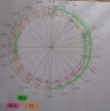
I'm better at visual than calculations, so I made a compass wheel.
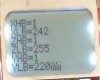
I can now see a pattern that will help me figure it out. There are 4x circles corresponding to XHB, XLB YHB, YLB
Hope it helps.
C
Did you have the compass, magnets or iron... near the chip when measuring.
Currents near the chip might affect the results?
HMC5983 has a self test feature, which you could try.
Hi J,
Regarding the self test feature. Does the module need to be in it's finished set-up, i,e, in the hardware, for the self test to work, or if I run it, will it work for all circumstances?
C.
Hi,
I'm getting a bit more familier with the 3 Axis compass technology, as time goes by, and getting various results. It seems as though there are two ways of compensating for errors. 1/for hard iron affects and 2/ For soft iron affects.
This site uses cookies to help personalise content, tailor your experience and to keep you logged in if you register.
By continuing to use this site, you are consenting to our use of cookies.