Continue to Site

Welcome to our site!

Electro Tech is an online community (with over 170,000 members) who enjoy talking about and building electronic circuits, projects and gadgets. To participate you need to register. Registration is free. Click here to register now.

  • Welcome to our site! Electro Tech is an online community (with over 170,000 members) who enjoy talking about and building electronic circuits, projects and gadgets. To participate you need to register. Registration is free. Click here to register now.

Compact DC heater using PID algo.

Status
Not open for further replies.

mananshah93

New Member
Hi to all Techno-crats.....:)


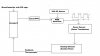
I want to design Heater which can produce heat around 25 to 600 Celcius using DC source.(Please see block diagram in attached file before reading.)
(1) I have a Kanthal Plate as a Heating Element.
(2) I don't know how to calculate power requirement for generating this amount of heat.
(3) I want to use PID algorithm for controlling close loop system where, thermocouple as a feedback sensor. I have a Atmega 16 microcontroller.
(4)Now, for generating power equivalent to desired temperature, I have planned following flow....

(A)Microcontroller will send command to 12 bit DAC(0 for min. and 4095 for max. power)
(B)12 bit DAC will generate analog voltage according to the input from controller.(0 to 12V)
(C) Now, using this voltage I want to generate PWM signal for 24 V source(or any value DC , not specific 24V).
(D) then, this PWM signal will be given to the power generator like power transformer to heat the kanthal plate. (is this making sense?:confused:)
(E) And temperature will be sensed by thermocouple and feedback to controller..and again using PID algorithm...It repeats and maintains the temperature...

Is this making sense????? Can you guide me regarding PWM generator and power generator part...
 

Attachments

  • Block Diagram-Heater.jpg
    Block Diagram-Heater.jpg
    21.7 KB · Views: 1,519
The Atmega16 can generate a PWM signal, read the PDF for the exact registers you need to setup to do this, the frequency isn't excessively important in your application. The simplest power driver for a heating element is simply a large logic level Mosfet that can handle the current your heating element can take. You adjust the duty cycle of the PWM to control the output power.

Your power requirements depend on the material you're heating, how fast you need to heat it and how insulated it is. Reading a thermocouple is going to require cold junction calibration and an amplifier.

What exactly are you heating? 600 C is pretty toasty.

I am developing this instrument for scientific experiment , in which user wants to heat their samples upto specific temperature and hold it for a while for reading,...i dont get your "600 C is pretty toasty"...what are you trying to say?

Regarding pwm in Atmega16, I haven't used it yet,,,,but this 5v pulse from same will be able to drive power mosfet...or power device(current rating??)...if yes can you give me that device no..and if possible schematic of what you are trying to say....
 
.i dont get your "600 C is pretty toasty"...what are you trying to say?
.
600C is dark red hot (about the temperature of an electric stove burner on high). Sounds toasty to me.
 
Why do you need the hassle of PID? You won't have a large load or rapidly changing load.
\

I have n't designed yet, I will design if it is required ...but I want help in PWM and Power generator part...

My specification are:

24V DC source---now I will change duty cycle of 24V using pwm...and using high frequency transformer(around 50kHz) I want 100Amps. 1V at secondary side to heat ....
 
I am developing this instrument for scientific experiment , in which user wants to heat their samples upto specific temperature and hold it for a while for reading,.......

mananshah93,

What's the voltage and current spec's for the Kanthal plate? I'm not sure why you want to PWM 24VDC to drive a transformer to drive a heating element. ???

If this is for a real research application, you will be time and money (if time is indeed money) ahead by going on eBay and buying a new/used/old-stock PID temp controller and a solid state relay. Like: PID temperature controller, Business Industrial, Computers Networking items on eBay.com

Reinventing the wheel is only useful if you want to know how wheels are made...including all the ways of doing it wrong. ;)

Ken
 
Last edited:
mananshah93,

What's the voltage and current spec's for the Kanthal plate? I'm not sure why you want to PWM 24VDC to drive a transformer to drive a heating element. ???

If this is for a real research application, you will be time and money (if time is indeed money) ahead by going on eBay and buying a new/used/old-stock PID temp controller and a solid state relay. Like: PID temperature controller, Business Industrial, Computers Networking items on eBay.com

Reinventing the wheel is only useful if you want to know how wheels are made...including all the ways of doing it wrong. ;)

Ken
It is a project, so I can't buy it and I don't want to...
ok then, can you suggest me something if you want around 600 degree Celcius temp. maximum, using DC source(any voltage) and then maintain particular temp. without on/off algo.,......how will you approach???
 
By "project" do you mean an academic exercise?

First step...same question..."What's the voltage and current spec's for the Kanthal plate?"
Second...How accurately, at 600C, must the controller maintain temp?...+/-1C?...+/-10C?...think real world.
Third...Is the Kanthal plate in an insulated container or open to ambient air? Consider the thermal mass of the plate in its environment.

Build your specifications first, then we can look for possible solutions to build.

Ken

so far...kanthal plate requires 100W ...error temp. must be ≤±1 degree celcius. and kanthal plate will be in the container...

now regarding smps transformer...i am looking forward for this kind of transformer shown in a link...https://www.electro-tech-online.com/custompdfs/2009/05/e6355_srw.pdf

my idea for controlling the power is shown in the link.
**broken link removed**
 
Again..."What's the voltage and current spec's for the Kanthal plate?" 100 watts is the power...4A@25V?...0.8A@120V?...or even the resistance of the element?

"≤±1 degree celcius" @ between 25C and 600C is going to be a real challenge. I wish you luck.

now regarding smps transformer...i am looking forward for this kind of transformer shown in a link...https://www.electro-tech-online.com/custompdfs/2009/05/e6355_srw-1.pdf

my idea for controlling the power is shown in the link.
Flyback transformer tutorial: function and design | EMS, OEM and ODM news and articles

In that case you will need to find someone that has expertise in designing variable output SMPS's.

Ken
 
Again..."What's the voltage and current spec's for the Kanthal plate?" 100 watts is the power...4A@25V?...0.8A@120V?...or even the resistance of the element?

"≤±1 degree celcius" @ between 25C and 600C is going to be a real challenge. I wish you luck.


In that case you will need to find someone that has expertise in designing variable output SMPS's.

Ken

I have asked about voltage and current to senior...he said 100Amps. 1 V..
but why? still I don't know... may be I²R....

In that case you will need to find someone that has expertise in designing variable output SMPS's.

Ken

why variable output?? as far as I know ideally or theoritically I am giving the same output to plate but what I am changing is the duty cycle of the output by controlling the mosfet switch connected to flyback transformer....am I right???
 
I have asked about voltage and current to senior...he said 100Amps. 1 V..
but why? still I don't know... may be I²R....
I agree, that doesn't seem right. I think you had better get that specification absolutely verified before you proceed.
why variable output?? as far as I know ideally or theoritically I am giving the same output to plate but what I am changing is the duty cycle of the output by controlling the mosfet switch connected to flyback transformer....am I right???
We may have a confusion about the power supply design you are planning on using. Can you post a schematic or link?

Ken
 
Status
Not open for further replies.

Latest threads

New Articles From Microcontroller Tips

Back
Top