Continue to Site

Welcome to our site!

Electro Tech is an online community (with over 170,000 members) who enjoy talking about and building electronic circuits, projects and gadgets. To participate you need to register. Registration is free. Click here to register now.

  • Welcome to our site! Electro Tech is an online community (with over 170,000 members) who enjoy talking about and building electronic circuits, projects and gadgets. To participate you need to register. Registration is free. Click here to register now.

CMOS 4510 BCD counter

Status
Not open for further replies.
Can anyone help me connect up this IC?!

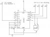
I am trying to make a clock, and I am using these counters, CMOS CD4510 Divide-By-10 BCD Up-Down Counter, to drive 7 segment displays as my O/Ps.

As with all my projects I am simulating first, to check my design, and oh look I have managed to make a mistake somewhere! Having read the data sheet for it, I understand that if you want it to count up and produce a BCD O/P you have to hold low the following pins Load, Carry In, Up/Down & Reset. I am doing this and applying a nice steady clock pulse to the CLK pin, but yet nothing is appearing on the Q pins! Does anyone know where I am going wrong?!

If anyone would like to see a circuit diagram, I will post a cut down of it.
 
From your description, it sounds like you have everything in order. However, it would help to see your schematic (or relevent section thereof) to make sure we haven't missed something. JB
 
CD4510

nothing is appearing on the Q pins!
Does that mean zeros, don't cares or an unknown condition appears on the Q pins? Did you pulse the reset line high at the beginning of your simulation?
 
To count up, up/down needs to be held high. This should not prevent the outputs from changing.
What is your supply voltage? What are the amplitude, frequency, pulse width, and rise/fall times of your clock pulses?
 
Here is a cut out of the circuit showing one counter. There are actaully three in the circuit, but they all follow this configuration, so if I can get this bit working, the rest will be fine.

To answer your questions:
The Q pins are the O/P pins on the IC. The amplitude of the clock pulse is 5v, with a 12v supply voltage. In the finished circuit it will run at 1Hz, but in the simulation I have it running at 100Hz. As it is simulated it is a virtual clock pulse so its rise/fall times are zero!

I hope this all helps and you are able to give me some more advice!
 

Attachments

  • counter_436.jpg
    counter_436.jpg
    26.5 KB · Views: 3,219
Your clock voltage amplitude has to be (nearly) the same as your supply voltage.
What are the AND gate and the diode for?
 
Your clock voltage amplitude has to be (nearly) the same as your supply voltage
That may be the problem. The input switching threshold falls midway (45% to 55%) between the supply levels. You don't need the AND gate to reset the counter at 1010B, since the 4510 is a BCD counter (CD4516 is the binary version). Since the AND gate isn't needed, neither is the diode (there to isolate the AND gate output from ground). Why not power the circuit off 5V? CMOS runs slower as supply voltage is reduced, but you're only clocking it at 100Hz/1Hz, well below the 4510s' max operating speed @5V (2Mhz@5V vs. ~ 4.5Mhz@12V).
 
Thank you very much for all your help!

I still cannot get my BCD counter working, but I have managed to get the binary one doing it's stuff (4516) So I'm going to use that one instead.

Laroche73, having tested it in my simulator, it seems I do have to reset the counter with an AND gate and diode. If I don't, it counts up to D form 0. I wouldn't know how to tell the time with letters! :wink:

But again, thank you, all of you, for your suggestions and help. I can now get on with my project and, hopefully, get it all done and working.
 
CD4516

Yes, the binary version (CD4516) would require an AND gate & diode, or similar reset circuit, to count BCD. Not sure why your simulator counts to 0DH rather than 0FH without them, though.
 
If the IC has a Synchronous Load, you could make it into a decade (or any other modulo) without the gate by configuring the counter to count down.

Connect the Cout to the Load enable. Connect 1001 (ie. decimal 9) to the parallel inputs. When the count = 0, Cout will be true and this will cause the counter to change to 9 at the next clock pulse.

I am doing this from memory since I away from home at the moment and cannot look at the data sheet.

Len
 
I also don't understand why you are getting the results (or lack of them) that you are seeing. But in any case, you don't need the diode to GND.
 
unneeded diode

Right, the diode adds no functionality to the circuit. Just remove it, the AND gate output holds reset low until 1010B is reached. Note that if the counter powers up in a non-BCD state, it can take up to two clock cycles to reset. This is the same thing a 4510 BCD counter (minus the AND gate, in UP count mode) would do. Len's suggestion is useful if you want to generate counters of a given modulus, without caring about the output values. Not what you want here, since your clock would count backwards (assuming you're trying to build a 12/24 hr clock). It would be fine for a countdown timer, though.
 
Status
Not open for further replies.

New Articles From Microcontroller Tips

Back
Top