jcarruthers
New Member
Hi All,
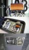
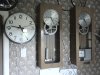
I've got an old Solari wall clock - huge thing that you see in train stations etc
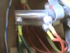
I got it "working" this morning by attaching a 6v power adapter - changing the polarity makes the clock work. It needs to go from +/- to -/+ to make the clock count "up" - uses an electromagnet to turn a weighted disc.
So what I need is an accurate timer circuit that will pulse every minute and go from +/- to -/+ - it can be off - then do the swapping polarity thing.
Any ideas? I don't think a 555 will be accurate enough for this...?
James
I've got an old Solari wall clock - huge thing that you see in train stations etc
I got it "working" this morning by attaching a 6v power adapter - changing the polarity makes the clock work. It needs to go from +/- to -/+ to make the clock count "up" - uses an electromagnet to turn a weighted disc.
So what I need is an accurate timer circuit that will pulse every minute and go from +/- to -/+ - it can be off - then do the swapping polarity thing.
Any ideas? I don't think a 555 will be accurate enough for this...?
James
")