Continue to Site

Welcome to our site!

Electro Tech is an online community (with over 170,000 members) who enjoy talking about and building electronic circuits, projects and gadgets. To participate you need to register. Registration is free. Click here to register now.

  • Welcome to our site! Electro Tech is an online community (with over 170,000 members) who enjoy talking about and building electronic circuits, projects and gadgets. To participate you need to register. Registration is free. Click here to register now.

Class-D amplifier

Status
Not open for further replies.

hanhan

Member
Hi,
Please help me with these questions:
Here is an article about class D amplifier in wikipedia: https://en.wikipedia.org/wiki/Class-D_amplifier

class-d-amplifier-modified-jpg.75353


Basic operation
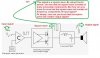
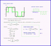
Class D amplifiers work by generating a variable duty cycle square wave of which the low-frequency portion of the spectrum is essentially the wanted output signal, and of which the high-frequency portion serves no purpose other than to make the wave-form binary so it can be amplified by switching the power devices.
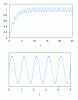
A passive low-pass filter removes the unwanted high-frequency components, i.e., smoothes the pulses out and recovers the desired low-frequency signal. To maintain high efficiency, the filter is made with purely reactive components (inductors and capacitors), which store the excess energy until it is needed instead of converting some of it into heat. The switching frequency is typically chosen to be ten or more times the highest frequency of interest in the input signal. This eases the requirements placed on the output filter. In cost sensitive applications the output filter is sometimes omitted. The circuit then relies on the inductance of the loudspeaker to keep the HF component from heating up the voice coil. It will also need to implement a form of three-level (class BD) modulation which reduces HF output, particularly when no signal is present.


Q2: Please help me explain the bold sentences? Why those frequencies help ease the requirements placed on the output filter?
 

Attachments

  • Class D amplifier (modified).JPG
    Class D amplifier (modified).JPG
    103.4 KB · Views: 1,963
If two frequencies are widely spaced (e.g. one is ten times the other) it is much easier to separate them than if they are close together.
 
Hi,

For Q1...

A simplified radio frequency modulator output is:
Vout=(1+cos(wm*t))*sin(wc*t)

where wm is the message signal angular frequency and wc is the carrier frequency angular frequency, and wm is always much less than wc. This reduces to:
Vout=sin(t*wm+t*wc)/2-sin(t*wm-t*wc)/2+sin(t*wc)

where we see the sum and difference frequencies and the carrier frequency. But this produces waves that are above and below zero at the carrier frequency.

In a PWM system like yours it's a little different because the half cycles are always above zero or below zero and follow the input wave shape, and this is a little difficult to think about it terms of frequencies but we can use a rough approximation to see what happens. The function we can use is:
Vout=(1+cos(wm*t))*(1+sin(wc*t))

and that reduces to:
Vout=sin(t*wm+t*wc)/2-sin(t*wm-t*wc)/2+cos(t*wm)+sin(t*wc)+1

were we can quickly spot the cos(t*wm) term, and that component is at the original input wave frequency.
If we filter this with a simple RC filter we get a wave that is always above zero but looking at the sinusoidal part alone we definitely see the original wave frequency as the diagrams below show.

In the diagrams, the carrier was 100Hz and the message signal was at 1hz. The one above is the actual output of the RC filter, and the bottom picture is the AC component amplified for clarity.
 

Attachments

  • ModulatedPWM.gif
    ModulatedPWM.gif
    8.5 KB · Views: 362
Thank you alec_t and MrAl.
If two frequencies are widely spaced (e.g. one is ten times the other) it is much easier to separate them than if they are close together.
I can understand the point that it is much easier to separate two frequencies that arre widely spaced. However, I don't see how triangular wave and input signal combined to create two frequencies mentioned above.
Can I consider comparator is an RF modulator?
Input signal is a baseband and triangular is a carrier. I can draw of output of the comparator but cannot write equation to express them.
A simplified radio frequency modulator output is:
Vout=(1+cos(wm*t))*sin(wc*t)

where wm is the message signal angular frequency and wc is the carrier frequency angular frequency, and wm is always much less than wc. This reduces to:
Vout=sin(t*wm+t*wc)/2-sin(t*wm-t*wc)/2+sin(t*wc)

where we see the sum and difference frequencies and the carrier frequency. But this produces waves that are above and below zero at the carrier frequency.
I get it but do you consider the comparator is a modulator here?
In a PWM system like yours it's a little different because the half cycles are always above zero or below zero and follow the input wave shape, and this is a little difficult to think about it terms of frequencies but we can use a rough approximation to see what happens. The function we can use is:
Vout=(1+cos(wm*t))*(1+sin(wc*t))

Could you elaborate about Vout function?
How can I get that?
 
hi anhnha,

Look at this plot of the comparator modulator, its very basic but it shows the modulated output.

The signal in is a50Hz sine wave and the triangular is approx 500Hz.

The modulated signal would be connected to a Res Cap demodulator.

E

EDIT: Changed the image to show the correct sine inp to mod output in same Phase.
 

Attachments

  • AAesp02.gif
    AAesp02.gif
    50 KB · Views: 408
PWM signal is nothing more than a square wave. Also the PWM average voltage is equal to:
Vavg = D *Vpeak Where D is a duty cycle D = Ton/(Ton + Toff). For example if we have 5V square wave with 50% duty cycle the average voltage is equal to 2.5V. To create average voltage from a PWM signal we use a low pass filter.
In class D amplifier comparator create at his output PWM signal proportional to the input signal. The larger the input signal the greater the duty cycle and vice versa.
For example if we have a 1V at the input, the PWM output duty cycle will be equal to 20% for 5V supply. If we change Vin to 2.5V the PWM duty cycle will change from 20% to 50%.
And if we back to 1V the PWM duty cycle will back to 20%.
And after the filter we get our original signal.
0.2*5V = 1V
0.5*5V = 2.5V
0.2*5V = 1V
So if input signal is a sine wave the PWM duty cycle will constantly changing in the rhythm of the input sine wave.
 

Attachments

  • pwm.PNG
    pwm.PNG
    36.6 KB · Views: 357
Thank you alec_t and MrAl.

I can understand the point that it is much easier to separate two frequencies that arre widely spaced. However, I don't see how triangular wave and input signal combined to create two frequencies mentioned above.
Can I consider comparator is an RF modulator?
Input signal is a baseband and triangular is a carrier. I can draw of output of the comparator but cannot write equation to express them.

I get it but do you consider the comparator is a modulator here?


Could you elaborate about Vout function?
How can I get that?

Hi,


PWM stands for "Pulse Width Modulation", so yes it is a modulation of sorts. But the more exact model requires lots of terms and Bessel functions for the most general variable message frequency case as we see in audio. So i gave you a function that behaves a little like that. It's not in any way an exact model, but behaves like the real thing and we can filter it and see what happens, and that is what i did. Mathematically it filters more easily too.
But perhaps to get closer to what you might like better, what we can do is model the system for one single input frequency. Then we should expect to see the output frequency the same as the input, and we will. BTW what you are seeking here appears to come under the general heading of spectral modeling because you are interested in what frequencies are present and what happens based on those frequencies.

So to start we can imagine the most superficial modulator, similar to what Eric showed, but our modulator will only produce one single pulse per half cycle. This is made with one single triangle per half cycle. If desired later on we can add more triangles which would produce more output pulses.

With only one pulse output centered at 90 degrees for each half cycle, we see one pulse go positive and one pulse go negative. To find the frequency components then we can use a simpler single dimensional Fourier analysis. This will show all the frequency components and we can limit what we look at to say the first 11 harmonics. What we will see is the pulse goes positive for maybe 2/3 of the first half cycle, then negative for 2/3 of the second half cycle (that's an approximation from memory but it will work just the same). And the frequency components we will see will include the fundamental frequency and that will be the highest amplitude, followed by smaller amplitudes of the 3rd, 5th, 7th, 9th, and 11th harmonics. The fundamental frequency will be the same frequency as our single frequency input signal. And we will also see the carrier frequency if it is higher than the fundamental which in this case it wont be, but if we add pulses later it will be present.

If you would like to explore this more, we can go right into the calculation which only involves a little bit of basic integration of a function. The more advanced variable frequency full blown form is much much more involved requiring probably a two dimensional Fourier analysis, but we dont really need to do that anyway.
 
Last edited:
hi anhnha,

Look at this plot of the comparator modulator, its very basic but it shows the modulated output.

The signal in is a50Hz sine wave and the triangular is approx 500Hz.

The modulated signal would be connected to a Res Cap demodulator.

E

EDIT: Changed the image to show the correct sine inp to mod output in same Phase.
Thanks Eric,
I knew this. I used PWM in a project with pic 16F877A to control the speed of a fan. My confused is why the modulated signal includes baseband signal.
 
Thanks Jony!
PWM signal is nothing more than a square wave. Also the PWM average voltage is equal to:
Vavg = D *Vpeak Where D is a duty cycle D = Ton/(Ton + Toff). For example if we have 5V square wave with 50% duty cycle the average voltage is equal to 2.5V. To create average voltage from a PWM signal we use a low pass filter.
I am wondering how can we design a low pass filter that allow only DC component and block all other components.
I have checked low pass filter frequency response. To meet the above requirement, the Q (quality factor) of the filter has to be infinite. This means that all component are ideal without parasitic resistance.
Is my understanding correct?

For example if we have a 1V at the input, the PWM output duty cycle will be equal to 20% for 5V supply. If we change Vin to 2.5V the PWM duty cycle will change from 20% to 50%.
And if we back to 1V the PWM duty cycle will back to 20%.
And after the filter we get our original signal.
0.2*5V = 1V
0.5*5V = 2.5V
0.2*5V = 1V
So if input signal is a sine wave the PWM duty cycle will constantly changing in the rhythm of the input sine wave.
Yes, in your example input signal is a DC voltage, therefore we can calculate output signal and check it easily.
But how about if input signal is a baseband signal with a range of frequencies. In this case, I failed to calculate output signal (after filter) and check it to make sure that output signal has the same shape with input signal.
 
Thanks MrAl,
I think you what meant can be illustrated by this picture:

fourier-series-of-a-square-wave-jpg.75370


I got it. But how about other cases:
1. Input signal is a single sinusoidal signal but triangular wave has higher frequency.
2. Input signal is a baseband signal with a range of frequencies and triangular wave has high frequency
 

Attachments

  • Fourier series of a square wave.JPG
    Fourier series of a square wave.JPG
    51.2 KB · Views: 1,375
I am wondering how can we design a low pass filter that allow only DC component and block all other components.
I have checked low pass filter frequency response. To meet the above requirement, the Q (quality factor) of the filter has to be infinite. This means that all component are ideal without parasitic resistance.
Is my understanding correct?
We will need ideal low pass filter, but we are unable to build such a filter even if we use ideal components.
Yes, in your example input signal is a DC voltage, therefore we can calculate output signal and check it easily.
But how about if input signal is a baseband signal with a range of frequencies. In this case, I failed to calculate output signal (after filter) and check it to make sure that output signal has the same shape with input signal.
But as you can see in my example I use a DC voltage but this DC voltage is changing with time. So we have a sort of a AC signal in time domain.
But this dos not change the basic principle of how the circuit is working. What is a different between my DC signal that change with the time and sinusoidal signal? Or yours baseband signal ? In time domain not a big difference. Because we can take a "snapshots" of a input signal and treat it as a DC signal.
The input signal don't change the principles of operation of a circuit.
 
We will need ideal low pass filter, but we are unable to build such a filter even if we use ideal components.
Can you tell me why it cannot be built even with ideal components?
But as you can see in my example I use a DC voltage but this DC voltage is changing with time. So we have a sort of a AC signal in time domain.
But this dos not change the basic principle of how the circuit is working. What is a different between my DC signal that change with the time and sinusoidal signal? Or yours baseband signal ? In time domain not a big difference. Because we can take a "snapshots" of a input signal and treat it as a DC signal.
The input signal don't change the principles of operation of a circuit.
That seems right! I will have to read more.
 
Hi Jony!
I have reread your post and now I see that output signal will constantly change in the rhythm of the input signal.
How about the case that duty cycle change constantly?
For example, in this picture D changes constantly, say D = 20% only for one cycle, next cycle D =30% and next cycle D =40% ... then how can I calculate output voltage?
I think we should compute average voltage over each cycle, right?
 
Hello again,

For a single bipolar pulse as shown in the attachment we simply change the limits of integration:
[LATEX]b_n=(2/L)\,\int_{A}^{B}\mathrm{f}\left( x\right) \,\mathrm{sin}\left( \frac{n\,\pi\,x}{L}\right) dx[/LATEX]

For multiple pulses as shown in the attachment we have to integrate over each pulse individually and add up all of the results:
bn=Sum(bnN over all k pulses)
[LATEX]b_n=\[\sum_{k=1}^{N}\mathrm{b}\left( k\right) \][/LATEX]

However we may have to also calculate the 'an' as well so we can account for the phase shifts (not shown in the drawing). When in doubt calculate those too and see if they are all zero or not.
 

Attachments

  • FourierPulses-1.gif
    FourierPulses-1.gif
    88.3 KB · Views: 344
Last edited:
I have reread your post and now I see that output signal will constantly change in the rhythm of the input signal.
How about the case that duty cycle change constantly?
For example, in this picture D changes constantly, say D = 20% only for one cycle, next cycle D =30% and next cycle D =40% ... then how can I calculate output voltage?
I think we should compute average voltage over each cycle, right?

hi anhnha,
This is the point I was trying explain in my post #5.

The pulse width reflects the instantaneous amplitude of the 'audio' signal that we wish to amplify in the 'D' class amplifier.

The Comparator output is a result of comparing the audio signal and the triangular 'sampling' frequency, which is a square wave of constant amplitude but with a varying pulse width.

This square wave is amplified in the 'D' class amplifier and is output as a square wave of greater amplitude.

To recover the amplified original audio signal the square wave signal is demodulated using a filter, usually a resistor/inductor capacitor network.

Consider the amplifier has to accept 'audio' over a range of 50Hz thru 10Khz, as shown at the highest audio frequency of 10KHz the triangular frequency would have to 100KHz.
ie: a ratio of 10 to 1.

As its only a 10:1 ratio, its not easy to 'faithfully' recreate the 10KHz audio signal due to the time constant constraints of the R/C demodulator

At lower frequencies the ratio becomes higher, so the audio signal will be closer to to original signal.

I realise you are seeking a mathematical solution, but I would say its important to bear in mind what is the purpose of the circuit.

Eric

This is an extract from your link.
The most basic way of creating the PWM signal is to use a high speed comparator ("C" in the block-diagram above) that compares a high frequency triangular wave with the audio input. This generates a series of pulses of which the duty cycle is directly proportional with the instantaneous value of the audio signal. The comparator then drives a MOS gate driver which in turn drives a pair of high-power switches (usually MOSFETs). This produces an amplified replica of the comparator's PWM signal. The output filter removes the high-frequency switching components of the PWM signal and recovers the audio information that the speaker can use.
 
Status
Not open for further replies.

Latest threads

Back
Top