Continue to Site

Welcome to our site!

Electro Tech is an online community (with over 170,000 members) who enjoy talking about and building electronic circuits, projects and gadgets. To participate you need to register. Registration is free. Click here to register now.

  • Welcome to our site! Electro Tech is an online community (with over 170,000 members) who enjoy talking about and building electronic circuits, projects and gadgets. To participate you need to register. Registration is free. Click here to register now.

Class AB amp help.

Status
Not open for further replies.

Lightium

Active Member
I was following this:

got this:
Screenshot at 2022-08-06 06-40-16.png


It's not running as expected.
 

Attachments

  • 27KHz_push-pull-osc.asc
    2.8 KB · Views: 202
Last edited:
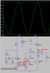
That design has some strange combinations of parts & values.

R5 is 47 Ohms, with ideally 5.4V across it idle or average, so just over 100mA standing current in the drive circuit. The average power in the driver transistor would be less than 1W at that, so why a 3055 which is 15A and low gain?

No adjustable bias means it's probably class B rather than AB, but for an oscillator that probably does not matter.

There is no bootstrap on the driver/bias chain so it's not going to be very linear, the positive peaks will distort or clip easily.

And worst thing, R9 will totally mess up the bias and dc feedback on the driver, Q1. It should have a capacitor in there.

Some time back I did a series of sequential mods to improve the generic internet design people keep using; it's supposed to be part of a youtube tutorial but I've not got all the actual amps built to match yet, so I've not completed the video..

Stage 0 is the original, then with bootstrap, adjustable bias & midpoint, higher gain power stage then differential input. All the transistor types are generic for the drawings.

Schematic_Basic Audio Amp - Stage 0.png


Schematic_Basic Audio Amp - Stage 1.png


Schematic_Basic Audio Amp - Stage 2.png


Schematic_Basic Audio Amp - Stage 3.png


Schematic_Basic Audio Amp - Stage 4.png
 
Most of your component values seem completely random and way outside of any sensible values - it seems a common issue with people who play with simulators.
It commonly takes longer for people who don't play with simulators to achieve the understanding they desire.
 
Increased R5 by 10:1 to get more gain.
Increased R9 to reduce gain. (sounds funny)
Increased R1 to bias the output near 6V.
Added R10 because the output was too large. Might have changed R6 with little effect.
Changed Q1, Q2, Q3 because I did not have the right parts.
1659793926121.png

1659794122876.png
 
Status
Not open for further replies.

Latest threads

New Articles From Microcontroller Tips

Back
Top