Continue to Site

Welcome to our site!

Electro Tech is an online community (with over 170,000 members) who enjoy talking about and building electronic circuits, projects and gadgets. To participate you need to register. Registration is free. Click here to register now.

  • Welcome to our site! Electro Tech is an online community (with over 170,000 members) who enjoy talking about and building electronic circuits, projects and gadgets. To participate you need to register. Registration is free. Click here to register now.

circuit info please

Status
Not open for further replies.

paulyt5966

New Member
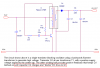
hi,i have built this circuit but im not sure how it works as im just a hobbyist so could some one please explain how the transistor makes the transformer oscillate,the transformer is a audio 100ohm to 1kohm with centre tap,the transistor is a tip41c and the diode from base to emitter is 1n914,the input is 9v dc battery and if i connect a high voltage capacitor across the secondry it will charge it to around 330v which i dont think is bad for such a simple circuit.[/i]
 

Attachments

  • transformer_648.jpg
    transformer_648.jpg
    59.8 KB · Views: 1,122
so all the experts on this site and no one can explain to me how this circuit works,sorry if its a waste of time but i like to not just build the circuits i get from books and the net but to understand how they work thats what its all about isnt it?
 
It's a simple blocking oscillator.

To oscillate a circuit requires positive feedback, and a gain greater than one - in this circuit the tapped primary provides the positive feedback, and the transistor provides the gain.

The drawback of this type of oscillator is that it uses a fairly expensive transformer, but when you need the transformer anyway (to step the voltage up), it's no longer a problem (except you require a transformer with a tapped primary!).
 
I looked at it and noticed that the transistor turns-on quickly due to the positive feedback through the transformer.
But the primary isn't tuned, so I think the transistor stays on and doesn't oscillate. :(
 
audioguru said:
I looked at it and noticed that the transistor turns-on quickly due to the positive feedback through the transformer.
But the primary isn't tuned, so I think the transistor stays on and doesn't oscillate. :(

But the OP has indicated it is working. He just want to know how it works.

Now to Paulyt5966, if you reverse the polarity of diode on the HV side(i.e.D2), do you think the circuit would still works?
 
Can you do a test and measure how high the positive voltage you can obtain in this configuration?
 
I still don't see anything that turns-off the transistor.
I am used to seeing circuits that actually work, like this one with a very important coupling capacitor:
 

Attachments

  • blocking_osc_that_works.png
    blocking_osc_that_works.png
    23.2 KB · Views: 955
well my circuit definately works as ive just tested it with d2 both ways around i get around 330v. might try and build your circuit now with my audio transformer and see what works best.
 
Here is a tuned blocking oscillator with the important "blocking" coupling capacitor:
 

Attachments

  • tuned_blocking_oscillator.png
    tuned_blocking_oscillator.png
    6 KB · Views: 969
I think it works like this:
The transistor turns off because the primary resistance is too low to support steady-state transistor saturation. It saturates when power is turned on, due to primary inductance, but as the inductor charges, eventually the collector voltage will start to rise due to the finite beta of the tranny. The positive feedback causes the base current (and voltage) to drop, turning the transistor off.
If the supply were to rise gradually, the lack of DC base current blocking would leave the transistor with Ic=beta*Ib, with no oscillation, which is Audioguru's scenario (I think). With a high beta transistor, the transistor could be destroyed due to overheating in this case.
I also think that the flyback voltage on the collector can be pretty high if the load is light, so care in picking the transistor is needed.
The frequency and output voltage are beta-dependent. It's sort of a minimalist blocking oscillator. Having the frequency determined by an RC time constant is much better unless it's just a one-off, and even then it's not a great idea.

Having said all that, I am no expert on blocking oscillators, so I may be full of crap. Here I am, speculating about the operation of a circuit - just the thing that have complained loudly about when others do it. I did run some sims on it to confirm my suspicions, but I don't think I've ever actually built a blocking oscillator. :roll:
 
maybe a stupid answer but what if the instant the current through r1
turns the transistor on it istantly switches off again because when
the current goes from collector to emitter this lowers the current enough to the base to switch it off and this repeats,does that make sense?
 
Hi Ron,
Thanks for your theory.
I also thought that when the transformer saturates then its current increases, and the transistor can't supply so much current which causes its collector voltage to rise.
Also when the transformer saturates then R1 no longer has double the supply voltage so the base current is halved.

Hee, hee. :lol: The transistor suddenly has a saturated "dead short" of the transformer to drive. The current is massive, causing the transistor to release a little of its majic smoke. Therefore it has lost some of its strength so it turns off to rest before conducting again. The puffs of smoke would sound like a motorboat. :lol:
 
I thought about inductor saturation, but I kinda thought that, with the 22k base resistor, the transistor would come out of saturation, due to beta, before the transformer core saturated. I guess it really depends on the properties of the core, and the beta of the transistor.
Perhaps they could make trannies with little smoke stacks on them for applications such as this. :)
 
Status
Not open for further replies.

Latest threads

New Articles From Microcontroller Tips

Back
Top