Continue to Site

Welcome to our site!

Electro Tech is an online community (with over 170,000 members) who enjoy talking about and building electronic circuits, projects and gadgets. To participate you need to register. Registration is free. Click here to register now.

  • Welcome to our site! Electro Tech is an online community (with over 170,000 members) who enjoy talking about and building electronic circuits, projects and gadgets. To participate you need to register. Registration is free. Click here to register now.

CIRCUIT HELP!!!! ASAP

Status
Not open for further replies.

*Peter *

New Member
Hey Guys...

I'm making a very simple monostable 555 timer circuit. It consists of a Potentiometer, motor and two led.

upload_2015-11-30_16-3-12.png


The Problem I am Facing is the motor draws too much current out of the circuit and produces difficulty. How can I solve this by allowing the motor to have it's own indepentent power supply but is also being triggered by the 555 timer output Pulse..
Cheers


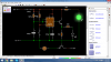
I have made a concept which may work, please tell me your thoughts :)

upload_2015-11-30_16-5-21.png
 

Attachments

  • upload_2015-11-30_16-2-41.png
    upload_2015-11-30_16-2-41.png
    182.1 KB · Views: 140
If you connect the collector of the transistor to the + ve of the power supply for the motor then it should work. (Providing the hfe of the transistor is high enough to provide enough current for the motor with the drive current available from pin 3 of the 555) You should give more information when asking a question. What is the voltage rating of the motor and the maximum current that will be drawn by the motor. You do not specify what the difficulty is. Is the motor drawing more current than the existing 9 volt power supply is capable of supplying or does the transistor not have enough current gain to drive the motor with the available drive current from the 555 ? Your second schematic will be worse than the first as the 10K resistorin series with the base will provide less drive than is available directly from pin 3 of the 555. If I was designing the circuit I would have put the motor in the collector circuit of the transistor rather than using the transistor as an emitter follower.

Les.
 
Ditch the NPN transistor and get a NFET (NMOS). The attached file has ~ 50 different ones available from Digikey that would work in your circuit.

If you rename the file back to NFets.csv, you can open it with Excel. Else open it with Notepad or any text editor...
 

Attachments

  • NFets csv.txt
    11.6 KB · Views: 168
Hi,

Mike:
Do you think you can post one more MOSFET please? 50 isnt quite enough but 51 should do it :)
Seriously though, why switch to a MOSFET? Yes that works, but so does the bipolar, right?

Peter:
You should connect your load to the collector (or drain of N-MOSFET), then run the motor to it's own positive power supply.
You probably also need a reverse diode to catch the back emf one the motor is turned off. Without that the transistor could blow.
 
To summarise what others are saying, I have redrawn your schematic.
555 and Motor.png

One thing I would comment on is your supply for the motor.
9 volts implies that you are using a small 9v battery, unless your motor is very small, the average 9v radio battery is just not up to the job, you need to use a battery with more Ooomph. *

JimB

* Ooomph - a technical term :D
 
Say the motor draws 3A (TS didn't know or didn't specify). If you use an NPN with the motor in the collector, the base current for for the NPN would have to be more than the 555 can supply (3A/10 = 300mA). To do it right, you would have to add an intermediate driver transistor or a Darlington, which agrivates the next problem: If you cheat, the NPN has a crummy Vcesat of >0.8V @3A, so it is dissipating 2.4W, so would have to bolted to a heatsink.

Now substitute an NFET. Say it has a Rdson of <30mΩ. It could be driven even from the CMOS 555 with no issue because it is voltage-driven; not current-driven. At 3A, it would dissipate I^2*Rds = 3^2*0.03 = 0.27W, so a TO220 tabbed NFET would not need a heatsink...

311.gif
 
Hi Mike,

Ok, makes sense. Good example.
 
Status
Not open for further replies.

Latest threads

New Articles From Microcontroller Tips

Back
Top