Mr RB
Well-Known Member
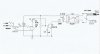
To Mike; I think that circuit has issues because all the power is fed as DC (only half a phase) and the sound card output is always capacitor coupled, and power needs to be drawn from it as AC.
To Camerart; Instead of using the bridge rectifier to draw AC power from the soundcard, you could eliminate that rectifier voltage drop and put the soundcard output through a series resistor into the LED, then put another LED in parallel (reversed!) with the first LED. That will draw balanced AC power but now there is no voltage drop from the bridge rectifier. For the final app use a LED in parallel reverse with the LED inside the optocoupler.
Also your voltages out of the sound card still seem low, you should check all volume controls in Windows (double click the volume icon and turn everything right up) and also it's possible your morse generating software has a volume control or does not output max volume for some reason?
") Laptops can have really wimpy sound output, basically they expect any speakers plugged into a laptop to be "powered" speakers (ie the speakers have their own amp).
Laptops can have really wimpy sound output, basically they expect any speakers plugged into a laptop to be "powered" speakers (ie the speakers have their own amp).