Continue to Site

Welcome to our site!

Electro Tech is an online community (with over 170,000 members) who enjoy talking about and building electronic circuits, projects and gadgets. To participate you need to register. Registration is free. Click here to register now.

  • Welcome to our site! Electro Tech is an online community (with over 170,000 members) who enjoy talking about and building electronic circuits, projects and gadgets. To participate you need to register. Registration is free. Click here to register now.

Circuit drawing double side.

Status
Not open for further replies.

Gregory

Member
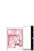
I have tried to get a circuit diagram for my C I G 195 mig welder but with no luck.
I am going to try and draw a circuit I have never don this . I will require help from time to time.
Can you tell me how do you draw a double sided board circuit.
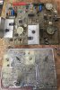
This is the circuit board in question .
I have posted this post in the wrong area.
I do not know how to move this post to PCB.
COULD someone move this post
Thank you
 

Attachments

  • 44937E01-82C9-442F-805F-9732A99AB883.jpeg
    44937E01-82C9-442F-805F-9732A99AB883.jpeg
    590.7 KB · Views: 176
Last edited:
It is probably best to work out the schematic first and then use one of the free pcb design programs to design a new board.

Mike.
 
The schematic will be the whole circuit of the board in one go.

The two sides of a board are generally to make it more compact and allow different connections to cross each other (on opposite sides).
 
Just follow the connection from where it leaves one component pin until it arrives at the next, regardless of which side it is or if it changes sides.

Spread things out well as you draw. You will probably end up re-drawing sections as you fill in more connections and the signal "flow" through different parts starts to make some sense, or when you get too many crossing connections on the drawing.
 
If you take good pictures of the board from top and bottom and flip the bottom picture left to right, you can draw a grid on them so you can easily see how connections go through the board. Can you draw and read a schematic?

Mike.
 
Because the CAD drawing is a windows I can not open it up in my I pad Can you assist me with this problem
 
I hate to say it but I think you're way out of your league. You're not going to be able to achieve what you want based on the level of experience you appear to have, based on your questions. Your best bet would probably be to buy a new welder, or at least a new control board.
 
What is wrong with the existing board? Maybe someone can help fixing it.

Mike.
 
It is a very old circuit board and has been repaired several times before, resulting in some damage to pads.

It looks like the two C122D thyristors have been changed before. I'd try swapping those and the two stud diodes on the same heatsinks.
It's a gamble but they are the main "high power" devices so most likely to fail if something is overloaded or overheated.
 
I have hand sketched the underside of the board and I will do the other side with components .
Could you check it out.
 

Attachments

  • 83332248-F051-4EF1-A15C-5F923696BF80.jpeg
    83332248-F051-4EF1-A15C-5F923696BF80.jpeg
    173.9 KB · Views: 165
If this is a multi-layer board then you are completely out of luck, because it's nearly impossible to know what the inner layers look like.

Have you ever heard the phrase "beyond economical repair"? Because I think that describes your welder, unfortunately.
 
Status
Not open for further replies.

Latest threads

New Articles From Microcontroller Tips

Back
Top