Continue to Site

Welcome to our site!

Electro Tech is an online community (with over 170,000 members) who enjoy talking about and building electronic circuits, projects and gadgets. To participate you need to register. Registration is free. Click here to register now.

  • Welcome to our site! Electro Tech is an online community (with over 170,000 members) who enjoy talking about and building electronic circuits, projects and gadgets. To participate you need to register. Registration is free. Click here to register now.

Circuit Design Verification

Status
Not open for further replies.

Sonia123

New Member
Hey there folks!

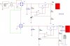
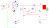
I am supposed to design a working device for supplying power to circuits aka power supply. In the attachment is the design that's done which would regulate voltage upto 55V (both positive and negative halves) and current upto 15A. Any feedback or constructive criticism would be highly appreciated since I am going to build it next week. Till then am so much looking forward for ideas from you people.
Thank you ^_^

P.S. I am unable to attach the .ms folder here so am taking a screen shot.
 

Attachments

  • project1.jpg
    project1.jpg
    83.6 KB · Views: 176
hi,
Look at the effect of connecting your two full wave bridges in reverse parallel will do.:eek:

EDIT:
Look at this image.
 

Attachments

  • AAesp04.gif
    AAesp04.gif
    31.1 KB · Views: 158
Last edited:
Hi Sonia123,

First: I haven't seen many OpAmps capable of a supply voltage of 55V. There are high voltage OpAmps on the market but they cost $$$.

Second: At 15A current flow both, positive and negative supply (smoothed using 220µ F) will produce an extremely high ripple voltage, usable to charge lead-acid-batteries, but not supply electronic circuits.

For low ripple voltage I normally select 4.700µF of filter capacitance per Ampere of current (70,500µF total).

For medium to good the value should not be worse than 2.200µF per Ampere. (still very high at 33,000µ
F).

The absolute minimum should not be below 1.000µF per Ampere. (15,000µF)

I wonder why you're planning for such a high output voltage. :confused:

It is normally not required for any circuit supply.

A safe output voltage of 24V (max 30V) should suffice in any case.

Using bipolar transistors for the power stages was yesterday (and some more days).

I suggest to redesign the circuit for ±24V and maximum currents of 5A and use MosFet transistors for the power stages. Bipolar transistors dissipate a lot of power at high current which requires a huge heat sink.

With a power supply as suggested you'll be able to cover 99% requirements for all circuits.

Just think about the problems involved as I pointed out.

Boncuk
 
Last edited:
Boncuk,

Can you elaborate more on OpAmp and I tried to change resistor value to lower down the voltage level. I don't know if that's the best idea but I got it working for the negative half cycle. For the positive half cycle, am getting voltage varying in the range of 96mV-98mV when am trying and I clearly don't know for what reason this is happening since it never happened before. Any idea?
Thanks for your reply and yes, I tried Mosfets instead of BJT.
Thanks again
 
Hi Sonia123,

your bridge rectifiers are shorted out.

Connect both in parallel and turn the negative branch upside down for a common ground.

I was not talking about BJTs for your circuit but power MosFet transistors.

No matter what input voltage you select for the OpAmps - they have to have a supply voltage the same as you take out of your circuit, which means they have to be high voltage OpAmps.

Here is a good link to search for high voltage OpAmps: http//www.datasheetarchive.com/

Put into the search window "high voltage operational amplifier".

You'll get a good selection of different brands and kinds of OpAmps.

Good luck

Boncuk
 
Hi,


Yeah i think Sonja did not understand Eric's post. He mentioned that when you connect the two bridges like that you effectively short out the power transformer secondary. In other words, you can not generate a plus and minus power supply using two bridge rectifiers like that.

Normally you would use a center tap transformer secondary and use the center tap as ground, and one bridge rectifier.
If you dont have a center tap transformer (only two leads from the secondary) then what you can do is go half wave, using two diodes from say the top transformer lead and grounding the other lead. One diode anode connects to the upper transformer lead (for positive supply voltage) and the other diode connects cathode to the upper transformer lead (for the negative supply voltage). The filter caps may have to be increased because then it will only be half wave rectification not full wave (half the frequency).
 
A picture (very simple schematic) is to be found in this post.
 
Boncuk,

Alright, so this is how I understand about the bridged transformers and OpAmp is chosen to be ideal in Multisim. Will se about it later on but currently am really confused about the placement of diodes in the design.
 

Attachments

  • pr.png
    pr.png
    23.5 KB · Views: 155
Last edited:
Grossel,

Thanks for the link. That's a very nice thing for designing simpler power supply. The problem is that am aiming for the one supplying higher voltage but anyways here's the initial sketch that I made in the same way which supplies voltage of 12V. Now am really confused about this stuff.
 

Attachments

  • power12V.JPG
    power12V.JPG
    81.8 KB · Views: 144
Grossel,

Thanks for the link. That's a very nice thing for designing simpler power supply. The problem is that am aiming for the one supplying higher voltage but anyways here's the initial sketch that I made in the same way which supplies voltage of 12V. Now am really confused about this stuff.

Sonia,
That circuit will just blow the power transistor

Correction.
Transistor will not conduct
 
Last edited:
Okay so I am soo much worried now regarding the first schematic. Am trying to redesign a new one again and any further brain flashes would be really appreciated.
 
Status
Not open for further replies.

Latest threads

New Articles From Microcontroller Tips

Back
Top