Continue to Site

Welcome to our site!

Electro Tech is an online community (with over 170,000 members) who enjoy talking about and building electronic circuits, projects and gadgets. To participate you need to register. Registration is free. Click here to register now.

  • Welcome to our site! Electro Tech is an online community (with over 170,000 members) who enjoy talking about and building electronic circuits, projects and gadgets. To participate you need to register. Registration is free. Click here to register now.

Circuit design help / suggestions needed.

Status
Not open for further replies.

nosliwsg

New Member
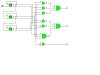
I need to design a circuit to create the following blink pattern in 3 LEDs (numbered 1,2,3)

1- 1 0 0 0 1 1 1
2- 0 0 1 1 1 1 0
3- 0 1 1 0 0 1 1

This pattern would need to be interrupted by all LEDs off for approx .5 seconds, and would repeat after the 7 sets.
With the timing being approximately 1 second on .5 seconds off (space between patterns)
I am hoping to do this with as simple a circuit as possible and am planning to convert it to a PCB once I have it built.
Any suggestions?
Thanks
Greg
nosliwsg@mac.com
 
Does it have to create that sequence for a specific reason or do you just need it to look random?
 
I'd code up a PIC 16F84. That would be easiest, and the PIC could drive the LEDs.
 
it is a specific pattern.

In response to the question, it is a specific pattern for a prop that is being built.
 
Never done PIC programming, is it hard?

I've never done any eeprom programming, and it's been years since I've done any computer programming at all (basic pascal and fortran were the only ones I ever learned). If anyone has any suggestions on how to learn the programming aspect of PIC's quickly I would greatly appreciate the help. I need to have this project done by the end of August (Plan to have the finished project on a PCB and installed into the application Prop by then) The total dimensions for the prop are 6x6x1.5 with the lights being placed on the 6x6 face. hopefully the pcb could be small enought to allow an additional circuit inside the box along with powersupply a few other lights.
If someone might be willing to program a PIC chip for me it would potentially help this project out (I would be willing to pay for the chip and programming time... within reason)
Thanks
Greg Wilson
 
Assembly coding for PICs is a PIECE OF CAKE!!!! Go to the Microchip web side and you'll find a TON of programming resources, including MPLab IDE - Which is a program for programming and Flashing the controllers. I would also recommend the book "Easy PIC'n" as a great place for a beginner to start. Once you see how easy it is, you’ll FLIP! And, the project you’re talking about will only take ya a few minutes to code. :wink:
 
If you want to do it without programming (and sacrifice the flexibility that programming offers), you can do it with 5 small chips. The schematic is below. I haven't built it or even simulated it, so there may be errors in it, but I don't think there are. You will still have to add resistors and/or transistors and LEDs. The complexity depends on how much drive you need for the LEDs.
All the LEDs will go off for one clock period.
 

Attachments

  • gates.gif
    gates.gif
    9.8 KB · Views: 546
Well Ron, nice to see somone excersising their mind and doing things the old fashioned way! Anyway, I took the liberty to copy your circuit to a simulator and check I didn't get the expected result (I may have made a mistake somewhere!) so I may try again tomorrow!
 

Attachments

  • logic.jpg
    logic.jpg
    27.5 KB · Views: 563
olly_k said:
Well Ron, nice to see somone excersising their mind and doing things the old fashioned way! Anyway, I took the liberty to copy your circuit to a simulator and check I didn't get the expected result (I may have made a mistake somewhere!) so I may try again tomorrow!
Olly, you're right. I forgot that, in order to get an up counter, I have to clock successive stages off the /Q output of the previous stage. What I had was a down counter. I've edited the schematic to reflect this. Let us know if you simulate it with the changes.

Thanks,
Ron
 
I'll try it out tonight.

I picked up the chips today and will put the circuit together tonight and test it out. This sounds exactly like what I need. I'll post once I have it up and running.
 
Status
Not open for further replies.

Latest threads

New Articles From Microcontroller Tips

Back
Top