Continue to Site

Welcome to our site!

Electro Tech is an online community (with over 170,000 members) who enjoy talking about and building electronic circuits, projects and gadgets. To participate you need to register. Registration is free. Click here to register now.

  • Welcome to our site! Electro Tech is an online community (with over 170,000 members) who enjoy talking about and building electronic circuits, projects and gadgets. To participate you need to register. Registration is free. Click here to register now.

Circuit design for HVAC to trigger ceiling fan.

Status
Not open for further replies.

Chris75

New Member
When my heating system kicks on I want it to trigger a ceiling fan turn on, and stay on until the heat turns off, via the remote control. I would like to use the thermostat's white wire as this gets energized to +24V AC when the heat goes on.

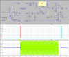
So, I'm looking for a kind of relay circuit that looks like this:

+24V AC shall momentarily close the remotes "Fan On"contacts.
0V AC shall momentarily close the remotes "Fan Off"contacts.

Basically, like hitting 'Fan on' when the heat turns on and hitting 'Fan off' when the heat turns off.
Constant voltage won't do because that's like keeping the remote button depressed the whole time the heat is on.

I've looked into timed relay's (for the momentary action) but it only get's me through half of my idea. It's turning the fan off that's got me stumped.


Any advice would be much appreciated.


Chris
 
Hi Chris75,

welcome to the forum.

Would a steady signal also suffice? If yes, I probably got a suitable circuit for you.

Boncuk
 
Are you going to hack into the remote to wire the relay contacts across the buttons? Do do still want to be able to push the buttons manually to turn on the fan at other times?

I have a way of doing what you want, but it's moderately complicated. You will need access to three wires from the furnace; both sides of the 24Vac control transformer as well as the wire switched by the thermostat. You will need some diodes, filter capacitors, a LM7812 voltage regulator, a CMOS Schmitt-trigger hex inverter, a couple of transistors, and possibly two small 24Vdc relays.

If this is something you want to build, I'll draw up a schematic.
 
Thanks Mike.

I was going to solder into the remote but away from the rubber button contacts so they can still be used. So manual control is something that I would like to have.

I can access (at the transformer itself) the wire that is switched by the stat as well as the red wire that has the +24Vac. By "both sides of the transformer" do you mean + as well as gnd?

Wow, I would love a schematic! Loss for words here...
 
Ok stare at this: I didn't show the interface to the buttons, but if you can tie the - battery terminal of your push-button remote to the ground of the controller, then you can do it without relays; you could either use just two isolation diodes, or two transistors, NPN or NFets.

Measure the voltage across an open push button, and measure the battery voltage in the remote, and I can add the interface between the controller and the remote.
 

Attachments

  • FanController.png
    FanController.png
    41.4 KB · Views: 850
This is fantastic, many thanks. Wish I can engineer a design like this.

I'm at work so I can't give you that info on the remote. When you say to measure the batt voltage in the remote, is 9V the answer your looking for since it's a 9V battery? Or is the voltage perhaps stepped up, or down? I have to take a closer look at the remotes board and get back to you by Monday the latest.
 
The supply voltage for the remote could just be the 9v. Use a high impedance voltmeter to measure the voltage that appears across the pushbutton with the negative lead of the DMM referenced first to +9V, and then to the negative end of the 9V battery.
 
What about taking the single phase from the HVAC (at the HVAC itself) and put a solid state timer to turn on the cieling fan?
 
Why not just connect the ceiling fan to the blower of the furnace? Use a double pole switch to select between automatic with furnace or standard/manual.
 
Why not just connect the ceiling fan to the blower of the furnace? Use a double pole switch to select between automatic with furnace or standard/manual.

thats what I was thinking only having a timer on it. It's simple just running wires and adding some control devices. don't have to create complicated circuitry for a simple job
 
But he has to rewire part of the house.
 
But he has to rewire part of the house.

That is correct.


Hi Mike, I don't [know if] have a HiZ voltimeter. But when I used the auto detect* feature on my DMM this is what I got:

Button to 9V Batt+ = 0V
Button to 9V Batt- = 8.77V (and it indicated LoZ)(plus the LED on remote lit up for a moment)


*The auto detect feature has LoZ which zeros out ghost voltages.


With my DMM set to read VDC this is what I got:
Button to 9V Batt+ = 0V
Button to 9V Batt- = 9.10V (Remote's LED does not light up)


If this is of no help to you I can hunt down an electrician at my co. He should have the right meter.
 
Last edited:
Ok, using the DMM set to read VDC, put the Neg meter lead on the battery -. There should be two connections to the back of each button. Using the Pos lead of the meter, measure the voltage on both sides of the button; first one, and then the other. Now press the button, and make the two measurements again. This should provide four readings.
 
You kept put a '+' in front of 24vac. Most HVAC relays are 24 vac. You can put another 24 vac relay to run the ceiling fan.
 
This is what I got:

Button Off:
0V
9.10V

Button On:
0V
approx .300 - 1.5V (jumpy reading, different everytime I press the button)
 
Ok, that means no relays are necessary. We can use two transistors wired across the buttons. I'll modify the main circuit, but out of time tonight.
 
Requires tying the neg end of the battery in the remote to the common ground.
 

Attachments

  • FanController.png
    FanController.png
    20.9 KB · Views: 165
Doesn't the 24V section of the furnace just control the main gas valve and ignition of the burner? At least on any of the furnaces I've ever worked with this is how they worked.

The blower is turned on by limit switches (120V) in the heat exchanger unit. Again this is how it is on the I've worked on.
 
Status
Not open for further replies.

Latest threads

Back
Top